Welcome to Geometry Nodes!
Imagine creating a forest of thousands of trees where you can change every tree's height, branch pattern, and placement with a single slider. Or building a city with procedurally generated buildings that update instantly when you adjust parameters. Or creating patterns that would take hours to model manually, but regenerate in milliseconds. This is the power of Geometry Nodes—Blender's revolutionary procedural modeling system!
Geometry Nodes represents a paradigm shift in 3D modeling. Instead of manually modeling every detail, you build systems that generate geometry based on rules and parameters. It's visual programming for 3D—combining the flexibility of code with the intuitiveness of node-based interfaces. Whether you're creating architectural visualizations, motion graphics, game assets, or artistic installations, Geometry Nodes unlocks possibilities that would be impractical or impossible with traditional modeling!
Processing] B --> C[Output Geometry] D[Parameters
Sliders/Values] --> B E[Randomness
Variation] --> B style B fill:#3a3a3a,stroke:#333,stroke-width:2px,color:#fff style C fill:#4CAF50,stroke:#333,stroke-width:2px,color:#fff
🎯 What You'll Learn
- Geometry Nodes fundamentals: Philosophy, interface, and workflow
- Node-based thinking: How to approach modeling procedurally
- Core node types: Input, geometry, utilities, output
- Data flow: How geometry and attributes flow through nodes
- Creating modifiers: Building reusable Geometry Nodes systems
- Common patterns: Instancing, distribution, randomization
- Real-world examples: Practical Geometry Nodes setups
- Best practices: Efficient node trees and organization
⏱️ Lesson Details
- Estimated Time: 90-120 minutes
- Difficulty: Intermediate to Advanced
- Prerequisites: Lessons 1-9 (modeling fundamentals)
- Project: Build a procedural fence generator and scatter system
In This Lesson
🌐 What Are Geometry Nodes?
Geometry Nodes is Blender's visual programming system for creating, modifying, and analyzing geometry procedurally. Instead of manually modeling objects, you build node networks—visual flowcharts—that define rules and operations. Change a parameter, and the entire system updates instantly. It's like having a smart assistant that rebuilds your model based on your instructions!
The Core Concept
💡 Procedural vs. Manual Modeling
Manual Modeling (Traditional):
- You create geometry directly—select vertices, extrude, scale, etc.
- Example: Model 100 fence posts by duplicating and positioning each one
- Advantage: Direct control, intuitive for simple objects
- Disadvantage: Time-consuming for complex/repetitive work, changes require re-modeling
Procedural Modeling (Geometry Nodes):
- You create systems that generate geometry based on rules
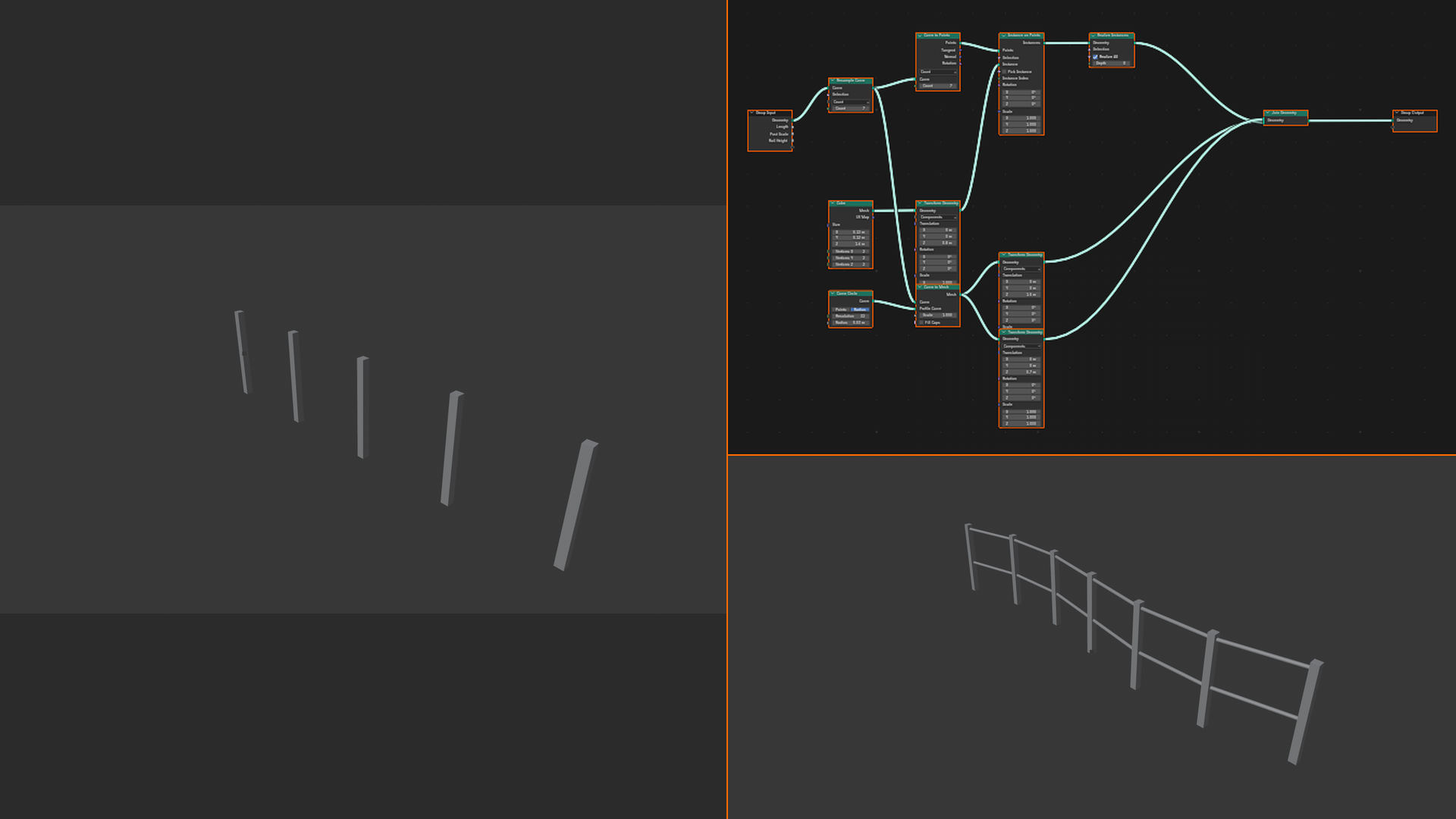
- Example: Build a "fence generator" that creates any number of posts automatically
- Advantage: Infinitely adjustable, handles complexity easily, non-destructive
- Disadvantage: Learning curve, requires thinking in systems rather than direct manipulation
The Magic Moment:
Manual: "I need 200 posts instead of 100" = Hours of work copying and positioning
Procedural: "I need 200 posts instead of 100" = Change one number, instant result!
🎬 Real-World Analogy: Think of manual modeling like painting a picture—every brushstroke is intentional and permanent. Procedural modeling is like writing a computer program that paints pictures—you define the rules once, then generate infinite variations. Want a different painting? Adjust the rules, don't start over!
What Geometry Nodes Can Do
🚀 Geometry Nodes Capabilities
Creation:
- Generate primitives (cubes, spheres, curves)
- Create meshes from scratch using math
- Build complex structures from simple rules
- Example: Procedural building generator, terrain systems
Modification:
- Transform existing geometry (move, rotate, scale)
- Deform meshes with noise, curves, fields
- Add details, subdivide, smooth
- Example: Parametric modifiers, animated deformations
Instancing:
- Copy objects thousands of times efficiently
- Scatter objects on surfaces (grass, rocks, particles)
- Distribute along curves (fences, cables, pipes)
- Example: Forests, crowds, architectural details
Analysis:
- Measure geometry (volume, surface area, edges)
- Detect properties (is point inside mesh? nearest surface?)
- Calculate relationships between objects
- Example: Adaptive systems that respond to geometry
Animation:
- Animated procedural effects
- Particle-like systems (but more powerful)
- Dynamic geometry that responds to scene changes
- Example: Procedural motion graphics, abstract animations
Geometry Nodes vs. Other Blender Systems
🔄 How Geometry Nodes Fits In
| System | Purpose | When to Use |
|---|---|---|
| Modifiers | Pre-built operations (Mirror, Array, Bevel) | Common modeling tasks with simple parameters |
| Geometry Nodes | Custom procedural operations (build your own!) | Complex custom systems, unique effects |
| Shader Nodes | Define material appearance (color, texture, shading) | Material creation (how objects look) |
| Compositor Nodes | Post-process rendered images | Final image adjustments after rendering |
| Particle Systems | Simulate many objects (old system) | Legacy—use Geometry Nodes instead! |
Key Point: Geometry Nodes is essentially a modifier—but instead of Blender giving you 30 pre-built modifiers, Geometry Nodes gives you the tools to build infinite custom modifiers yourself!
Materials/Appearance] A --> C[Geometry Nodes
Geometry/Structure] A --> D[Compositor Nodes
Post-Processing] style C fill:#3a3a3a,stroke:#333,stroke-width:2px,color:#fff
🎯 Why Procedural Modeling?
Before diving into the technical details, let's understand why procedural modeling matters. It's not just about speed (though that's a huge benefit)—it's about thinking differently about 3D creation. Procedural workflows unlock creativity in ways manual modeling can't. Understanding the "why" will help you recognize when to use Geometry Nodes versus when to stick with traditional modeling!
The Advantages of Procedural Workflows
✅ Key Benefits
1. Non-Destructive Editing
- Change parameters anytime without losing work
- Original geometry remains intact—nodes sit on top as modifiers
- Experiment freely, knowing you can always revert
- Example: Try 10 different fence post counts, pick the best, adjust spacing later
2. Instant Iteration
- Adjust sliders, see results immediately
- Client wants changes? Seconds instead of hours
- Explore variations effortlessly
- Example: Change building height from 5 floors to 50 floors—one slider
3. Handles Complexity Effortlessly
- Operations that would take days manually happen instantly
- 1000 objects? 100,000 objects? Same effort
- Complex calculations done automatically
- Example: Scatter 50,000 grass blades on terrain—Geometry Nodes handles it
4. Reusability
- Build once, use everywhere
- Save node groups as assets
- Share with team or community
- Example: Create "rock scatter" system, use on every terrain in every project
5. Randomness and Variation
- Generate unique variations automatically
- No two instances look identical (unless you want them to)
- Organic, natural-looking results
- Example: Forest where every tree is slightly different height/rotation
6. Animation-Friendly
- Keyframe node parameters for animated effects
- Geometry responds to scene changes dynamically
- Motion graphics become simple
- Example: Buildings growing from ground, procedural destruction effects
When to Use Geometry Nodes
🎯 Perfect Use Cases
Geometry Nodes Excel When:
- Repetition: Fences, windows, bricks, floor tiles—anything repeated many times
- Variation: Forests, crowds, cities—need uniqueness within similarity
- Parameters: Client might change requirements (building height, tree count, spacing)
- Distribution: Scatter objects on surfaces (grass, rocks, decorations)
- Patterns: Geometric patterns, fractals, mathematical structures
- Large scale: Hundreds or thousands of objects
- Reuse: System will be used multiple times across projects
- Motion graphics: Animated procedural effects
⚠️ When NOT to Use Geometry Nodes
Traditional Modeling Better When:
- Unique hero assets: One-off character or detailed prop needs artistic sculpting
- Organic shapes: Faces, creatures, natural forms require manual control
- Simple objects: Basic table/chair—faster to model directly than build system
- Artistic expression: You need direct "feel" of sculpting/modeling
- Client demands exact shape: No flexibility = procedural overkill
The Rule: If you're making ONE of something unique, model manually. If making MANY similar things with variation, use Geometry Nodes!
Real-World Applications
💼 Industry Examples
Architecture and Visualization:
- Procedural building facades (windows, balconies automatically placed)
- Parametric architecture (buildings with adjustable dimensions)
- Landscaping (trees, shrubs, ground cover scattered realistically)
- Urban planning (entire city blocks generated procedurally)
- Benefit: Clients can request changes late in process without cost
Game Development:
- Level generation (procedural dungeons, terrain, buildings)
- Asset variation (100 unique trees from one system)
- LOD systems (detail adjusts based on distance automatically)
- Modular kit systems (pieces snap together procedurally)
- Benefit: Massive worlds without massive artist time
Motion Graphics:
- Abstract animations (geometric patterns transforming)
- Text effects (letters scattering, reconstructing)
- Logo animations (procedural reveals and transitions)
- VJ loops (infinite variations from one system)
- Benefit: Keyframe parameters, not thousands of objects
Visual Effects:
- Destruction simulations (buildings crumbling procedurally)
- Particle replacements (complex instanced geometry)
- Growth effects (vines, crystals, organic spreading)
- Abstract environments (alien worlds, surreal spaces)
- Benefit: Art directable simulations
Product Design:
- Parametric products (furniture with adjustable dimensions)
- Pattern design (surface patterns, knurling, textures)
- Customizable designs (clients adjust parameters for custom versions)
- Manufacturing variations (different sizes from same design)
- Benefit: One design = infinite variations
The Procedural Mindset
🧠 Thinking Procedurally
Manual Modeling Mindset:
- "I will create THIS specific fence"
- Direct manipulation: Move vertex here, extrude there
- Concrete, immediate, tangible
- Thinking: "What actions do I take?"
Procedural Modeling Mindset:
- "I will create a SYSTEM that can make any fence"
- Define rules: "Post every X meters, crossbeam at Y height"
- Abstract, flexible, parameterized
- Thinking: "What rules define the result?"
The Shift:
- From "What do I make?" to "What system makes what I want?"
- From "How do I position these objects?" to "What rule positions objects?"
- From "This looks good" to "This range of values produces good results"
💭 The Learning Curve Truth: Geometry Nodes has a learning curve, not because it's complicated, but because it requires thinking differently. Once you "get" procedural thinking, it's incredibly powerful. The initial investment pays off exponentially—especially when you find yourself building systems in 10 minutes that would take days to model manually. Stick with it through the first few confusing moments. That "aha!" moment when procedural thinking clicks is transformative!
Geometry Nodes Success Stories
✅ What Professionals Say
Architectural Visualizer:
"We used to spend 2-3 days placing windows on building facades. Now with Geometry Nodes, we adjust a few parameters and it's done in seconds. When clients change the building height from 6 floors to 12, it's no longer a crisis—we just change a number."
Game Environment Artist:
"Our forest system uses Geometry Nodes to scatter thousands of trees with proper density falloff, random scaling, and biome-specific species. We can create an entire forest biome in an afternoon instead of weeks of manual placement."
Motion Graphics Artist:
"Before Geometry Nodes, complex motion graphics meant animating hundreds of objects manually. Now I keyframe a few parameters and get infinite variations. My clients love that I can show them 10 different versions in the time it used to take to make one."
Indie Game Developer:
"As a solo dev, I can't spend months modeling. Geometry Nodes lets me create procedural asset systems—rock generators, vegetation, building kits. I build the system once, generate thousands of unique assets. Game development is actually feasible now."
Common Misconceptions
⚠️ Myths About Geometry Nodes
Myth 1: "It's only for technical/math people"
- Reality: It's visual programming—no code required. If you can follow a flowchart, you can use Geometry Nodes.
- Many artists with zero programming experience become Geometry Nodes experts
Myth 2: "It's too slow/complicated for simple tasks"
- Reality: Start simple! A basic "duplicate along curve" setup takes 2 minutes
- You don't need complex systems to benefit from procedural thinking
Myth 3: "It replaces traditional modeling"
- Reality: It complements traditional modeling. Use both together!
- Model unique assets manually, then distribute them procedurally
Myth 4: "Results look generic/procedural"
- Reality: With good randomization and variation, results look organic
- Bad procedural looks procedural; good procedural looks hand-crafted
Myth 5: "Too performance-heavy for production"
- Reality: Geometry Nodes is highly optimized. Instancing is extremely efficient
- Thousands of objects that would crash old particle systems run smoothly
🎯 Why Procedural Summary
- Non-destructive: Change anything anytime without losing work
- Instant iteration: Adjust parameters, see results immediately
- Handles complexity: 1 object or 100,000—same effort
- Reusable systems: Build once, use forever
- Perfect for: Repetition, variation, distribution, patterns, large scale
- Not for: Unique hero assets, organic sculpting, simple one-offs
- Mindset shift: From "make this thing" to "make system that makes things"
- Industry-proven: Used in architecture, games, VFX, motion graphics
Ready to see the interface? Let's explore Geometry Nodes workspace!
🖥️ Geometry Nodes Interface
Time to get hands-on! The Geometry Nodes interface is where the magic happens. It's similar to Shader Editor—a node-based workspace where you connect boxes (nodes) with lines (connections) to build systems. If you've used Shader Nodes, you'll feel right at home. If not, don't worry—the interface is intuitive once you understand the basics. Let's explore the workspace and create your first node tree!
Opening Geometry Nodes Editor
✅ Getting Started
Method 1: Geometry Nodes Workspace (Recommended for Beginners)
- Top menu bar: Click "Geometry Nodes" workspace tab
- Blender automatically opens pre-configured layout
- 3D Viewport (top), Geometry Nodes Editor (bottom)
- Spreadsheet (right) for inspecting data
- This workspace is optimized for Geometry Nodes work
- Everything you need in one place!
Method 2: Manual Editor Switch
- Any editor window: Click editor type icon (top-left corner)
- Select "Geometry Node Editor" from dropdown
- Editor transforms into node workspace
- Use this method to add Geometry Nodes editor to custom layouts
Method 3: Split Screen
- Hover over editor corner until crosshair appears
- Drag to split screen
- Change new editor to Geometry Node Editor
- Work with viewport and nodes side-by-side
Geometry Nodes Editor Layout
🗺️ Understanding the Interface
Main Areas:
1. Header Bar (Top)
- Editor type menu: Switch between editor types
- Object selector: Choose which object's nodes to edit
- Modifier selector: If object has multiple Geometry Nodes modifiers
- New button: Create new node tree
- Pin icon: Keep current node tree visible even when selecting other objects
- View menu: Frame All, zoom options
2. Node Workspace (Main Area)
- Large grid where you add and connect nodes
- Pan view: Middle mouse button drag (or Shift + mouse drag)
- Zoom: Scroll wheel (or Ctrl + middle mouse drag)
- Frame all nodes: Home key (like viewport)
- Backdrop: Grid helps visualize space
3. Sidebar (N key)
- Item tab: Active node properties (appears when node selected)
- Tool tab: Group tools and options
- View tab: Overlays, grid settings
- Toggle visibility: Press
Nto show/hide
4. Add Menu
- Access:
Shift+A(like adding objects in viewport) - Categorized node list (Geometry, Mesh, Curve, Utilities, etc.)
- Search: Start typing node name to filter
- Most-used shortcut in Geometry Nodes!
Creating Your First Geometry Nodes Modifier
💡 Step-by-Step: Setup
Let's create a simple Geometry Nodes modifier:
- Start with an object:
- 3D Viewport: Add > Mesh > Cube (or use default cube)
- Object Mode, cube selected (orange outline)
- Switch to Geometry Nodes workspace:
- Top bar: Click "Geometry Nodes" tab
- Viewport shows cube (top), node editor empty (bottom)
- Add Geometry Nodes modifier:
- Node editor header: Click "New" button
- Or: Modifiers panel (right side) > Add Modifier > Geometry Nodes
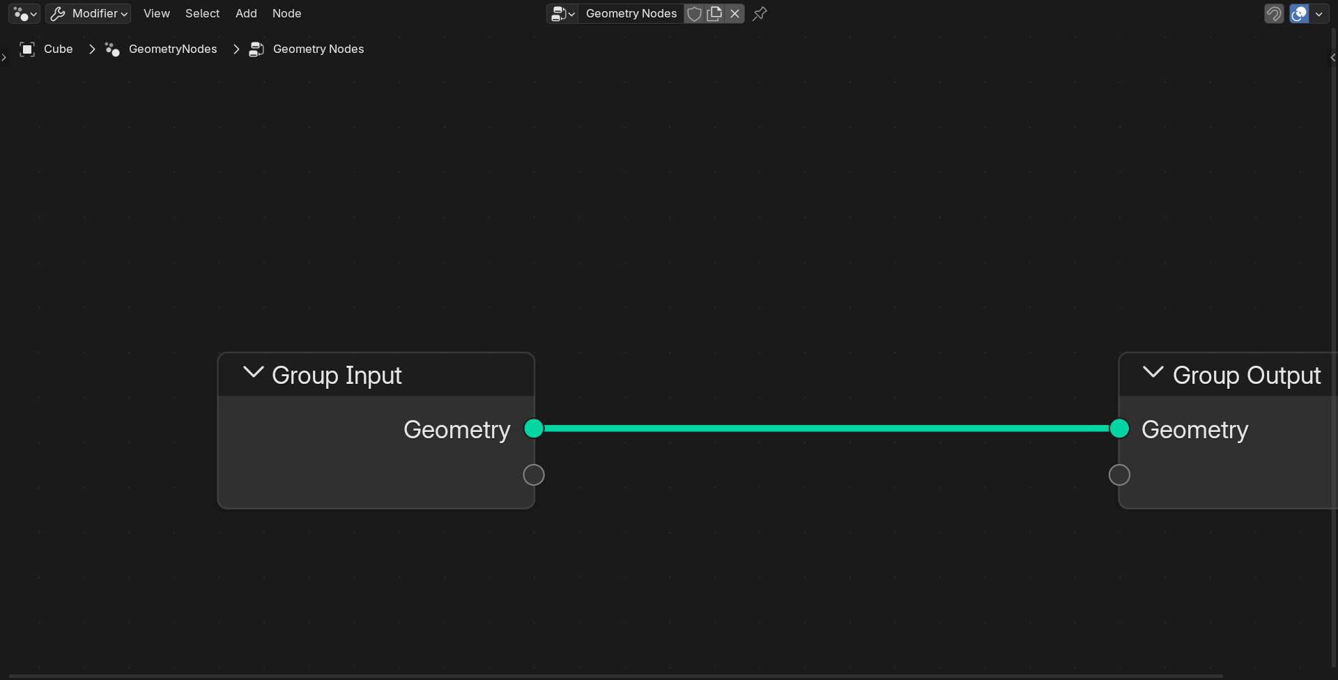
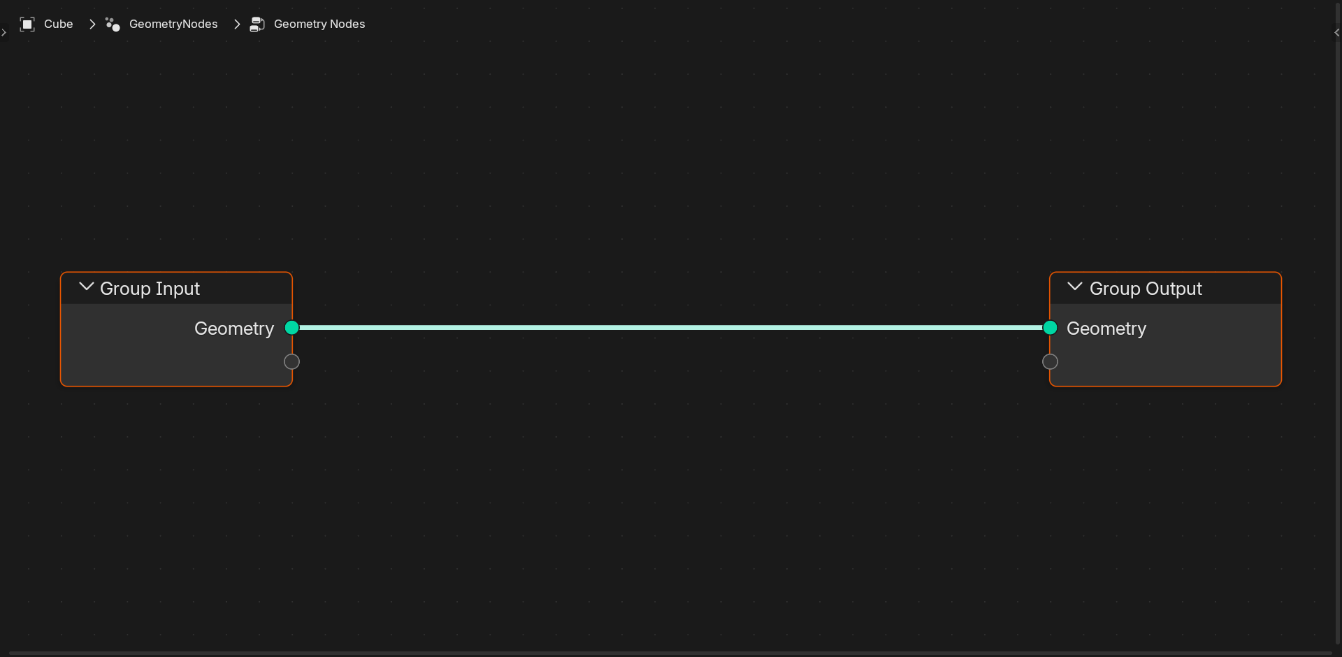
- Result: Two nodes appear automatically!
- What you see:
- Group Input node (left) - Where geometry enters
- Group Output node (right) - Where geometry exits
- Gray line connecting them (the data flow)
- Current behavior:
- Geometry goes in → passes through unchanged → comes out
- Cube looks identical (no nodes added yet)
- This is your blank canvas!
Important Notes:
- Geometry Nodes is a modifier (like Array, Mirror, Subdivision)
- Find it in: Modifiers panel, listed as "GeometryNodes"
- Original mesh unchanged—nodes modify a copy
- Can apply modifier to "bake" result (makes it permanent)
Node Editor Navigation
🎮 Essential Shortcuts
| Action | Shortcut | Notes |
|---|---|---|
| Add node | Shift+A |
Most-used shortcut! |
| Delete node | X or Delete |
Select first, then delete |
| Duplicate node | Shift+D |
Copies node and settings |
| Move node | G |
Grab and reposition |
| Select multiple | Shift+Click |
Add to selection |
| Box select | B |
Drag box around nodes |
| Cut connection | Ctrl+RMB drag |
Slice through connections |
| Mute node | M |
Temporarily disable |
| Frame all | Home |
Zoom to fit all nodes |
| Pan view | MMB drag |
Move around workspace |
| Zoom | Scroll wheel |
In and out |
| Search | F3 |
Search all operations |
Pro Tip: Same shortcuts as viewport navigation! If you know 3D Viewport shortcuts, you know node editor shortcuts.
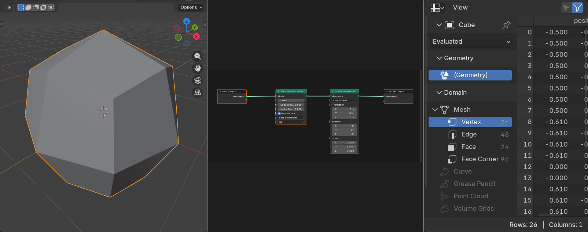
The Spreadsheet Editor
✅ Inspecting Geometry Data
What is the Spreadsheet?
- Shows geometry data in table format
- Every vertex, edge, face visible with all attributes
- Like "looking under the hood" of your geometry
- Essential for debugging and understanding data flow
Opening Spreadsheet:
- Geometry Nodes workspace: Already open (right side)
- Manual: Change editor type > Spreadsheet
- Or: Window menu > Toggle System Console (shows data)
What You See:
- Columns: Position, index, attributes, etc.
- Rows: Each vertex/edge/face/instance
- Header: Switch between Points, Edges, Faces, Instances
- Pin icon: Keep viewing specific geometry node (doesn't change when selecting nodes)
When to Use:
- Verify geometry was created (check point/face count)
- Inspect attribute values (are positions correct?)
- Debug why nodes aren't working (no data? wrong data?)
- Understand data structure (what am I working with?)
Beginner Note: You won't use spreadsheet constantly—but when something isn't working, spreadsheet shows you exactly what's happening with your data!
Interface Tips and Tricks
💡 Working Efficiently
Organization:
- Use frames:
Ctrl+Jgroups nodes in colored frame (organizational only) - Add reroutes:
Shift+RMBon connection creates reroute point (clean up spaghetti) - Node labels: Select node, press
F2to rename (documentation) - Color nodes: Right-click node > Color (visual categorization)
Workflow:
- Split screen: 3D Viewport and Geometry Nodes side-by-side (see results immediately)
- Pin frequently: Pin icon keeps current tree visible when selecting other objects
- Use viewer nodes: "Viewer" node lets you preview intermediate results
- Collapse nodes: Click arrow on node header to minimize (save space)
Learning:
- Hover tooltips: Mouse over any socket/property for explanation
- Node documentation: Right-click node > Online Manual (opens Blender docs)
- Example files: Blender ships with demo files (File > Open > Browse examples)
- Community assets: Download .blend files with node setups to study
💭 Interface Philosophy: The Geometry Nodes interface follows Blender's "everything is viewport" philosophy. Just like 3D Viewport, Shader Editor, and Video Sequencer all use similar navigation and shortcuts, Geometry Nodes feels familiar if you know other Blender editors. This consistency is intentional—learn once, apply everywhere. If you're comfortable with Shader Nodes, you're 80% of the way to comfortable with Geometry Nodes!
🎯 Interface Summary
- Access: "Geometry Nodes" workspace tab (pre-configured layout)
- Main area: Node workspace (add, connect, organize nodes)
- Add nodes: Shift+A (most important shortcut!)
- Navigation: Same as viewport (MMB pan, scroll zoom, Home frame)
- Spreadsheet: View geometry data in table format (debugging)
- Modifier: Geometry Nodes appears in modifiers panel like Array/Mirror
- Non-destructive: Original geometry unchanged, nodes process copy
- Tooltips/docs: Hover for help, right-click for manual
Interface explored! Now let's understand node anatomy!
🔍 Understanding Node Anatomy
Nodes are the building blocks of Geometry Nodes systems. Each node is a self-contained unit that performs a specific operation—create a cube, move geometry, scatter instances, perform calculations. Understanding how nodes work—their inputs, outputs, and settings—is fundamental to building anything in Geometry Nodes. Let's dissect a node and understand every part!
Parts of a Node
🧩 Node Components
Every node has these elements:
1. Node Header (Top Bar)
- Node name: What this node does (e.g., "Set Position", "Mesh Cube", "Join Geometry")
- Icon: Visual indicator of node type (geometry, utility, math, etc.)
- Collapse arrow: Click to minimize node (save space)
- Color: Category color-coding (green = geometry, blue = input, orange = geometry operations)
2. Input Sockets (Left Side)
- Small circles/diamonds on left edge
- Where data enters the node
- Connect output from another node here
- Each socket has a specific data type (geometry, number, vector, color, etc.)
- Can have default values (used if nothing connected)
3. Output Sockets (Right Side)
- Small circles/diamonds on right edge
- Where data exits the node
- Connect to input of another node
- One output can connect to multiple inputs (data can split)
- Each socket has specific data type
4. Parameters/Settings (Middle Area)
- Input sockets with no connection show as editable fields
- Number fields, sliders, dropdowns, color pickers
- Adjust values to change node behavior
- Some nodes have few parameters, others have many
5. Node Body
- Background area containing all elements
- Can be colored for organization
- Can be moved, duplicated, deleted
- Size adjusts based on content
Data Types and Socket Colors
💡 Understanding Socket Colors
Sockets are color-coded by data type:
- Green: Geometry (meshes, curves, point clouds, instances)
- The main data flowing through most node trees
- Can contain vertices, edges, faces, attributes
- Gray: Float (single number, like 3.14 or 100)
- Used for distances, scales, weights, etc.
- Most common numeric type
- Purple: Vector (three numbers: X, Y, Z)
- Used for positions, directions, rotations, scales
- Example: (1.0, 2.5, -3.0)
- Dark Gray: Integer (whole number, like 5 or 42)
- Used for counts, indices, seed values
- No decimals allowed
- Yellow: Color (RGBA values)
- Used for vertex colors, material inputs
- Four values: Red, Green, Blue, Alpha
- Green (lighter): Boolean (True/False)
- Used for on/off switches, conditions
- Shows as checkbox when unconnected
- Pink: String (text)
- Used for names, labels, attribute names
- Example: "position", "my_attribute"
- Orange: Material
- Material shader trees (link to Shader Editor)
- Assign materials to geometry
- Purple (darker): Rotation
- Specific rotation data (Euler or Quaternion)
- Different from regular vectors
- Diamond shape: Field (special type)
- Value that can be different for each point/element
- Example: random value per instance
Connection Rule: Can only connect sockets of compatible types. Green to green, gray to gray, etc. Blender won't let you connect incompatible types (connection won't attach).
How Nodes Process Data
✅ The Flow of Data
Nodes work like an assembly line:
- Input arrives at left sockets
- Data comes from connected nodes or default values
- Multiple inputs possible (geometry + parameters)
- Node performs operation
- Executes its specific function using inputs
- Example: "Set Position" node moves geometry based on offset input
- Output exits at right sockets
- Result of operation available to other nodes
- Can output multiple types (geometry + selection + value)
- Flows to next node
- Output connects to another node's input
- Process repeats through entire tree
Example Flow:
Group Input (Geometry) → Set Position (moves it) → Join Geometry (combines with other) → Group Output (result)
Key Concept: Data flows LEFT to RIGHT through the tree. Think of it like reading a sentence—start on the left, follow the connections, end on the right.
Node Categories
📚 Types of Nodes
Geometry Nodes are organized into categories (Shift+A menu):
Input Nodes (Create Geometry):
- Primitives: Mesh Cube, UV Sphere, Cylinder, Cone, Grid, etc.
- Generate basic shapes from scratch
- Curve primitives: Curve Circle, Bezier Segment, Spiral, etc.
- Generate curves and lines
- Scene: Collection Info, Object Info
- Pull objects/collections from scene
- Constants: Value, Integer, Vector, Color
- Create specific values for use in tree
Geometry Nodes (Modify Geometry):
- Transform: Set Position, Transform Geometry, Scale Elements
- Move, rotate, scale geometry
- Operations: Join Geometry, Merge by Distance, Delete Geometry
- Combine or remove geometry
- Mesh: Subdivide Mesh, Extrude Mesh, Dual Mesh
- Mesh-specific operations
- Curve: Resample Curve, Trim Curve, Fillet Curve
- Curve-specific operations
- Instances: Instance on Points, Realize Instances
- Create and manage instanced geometry
Utilities Nodes (Math & Logic):
- Math: Math node (add, multiply, sin, cos, etc.)
- Perform calculations on numbers
- Vector: Vector Math (add vectors, dot product, etc.)
- Calculations involving 3D coordinates
- Color: Mix, RGB Curves, Hue/Saturation
- Manipulate color values
- Utilities: Map Range, Clamp, Switch, Compare
- Remap values, create conditions
- Text: String to Curves, Join Strings
- Work with text data
Attribute Nodes (Read/Write Data):
- Store/Capture: Store Named Attribute, Capture Attribute
- Save data on geometry for later use
- Remove: Remove Named Attribute
- Delete stored data
- Special: Position, Normal, ID, Index
- Access built-in geometry data
Material/Texture Nodes:
- Material: Set Material, Replace Material
- Assign materials to geometry
- Texture: Image Texture, Noise Texture, Voronoi
- Generate or sample textures for data
Common Node Patterns
💡 How Nodes Connect
Pattern 1: Linear Chain
Input → Node A → Node B → Node C → Output
- Data flows straight through, each node modifying result
- Example: Input Cube → Scale → Rotate → Subdivide → Output
- Most common pattern for simple operations
Pattern 2: Branching
         → Node B →
Input →             → Join → Output
         → Node C →
- One input splits to multiple paths, then recombines
- Example: Input Cube → (Scale large + Scale small) → Join → Output
- Used when creating variations or parallel processing
Pattern 3: Multi-Input
Node A →
         → Node C → Output
Node B →
- Multiple sources feed into one operation
- Example: (Cube + Sphere) → Join Geometry → Output
- Common with Join, Mix, and combination nodes
Pattern 4: Parameter Control
Input Geometry →
                  → Set Position → Output
Value Node     →
- Separate nodes provide parameters to main operation
- Example: Cube → Set Position (controlled by Math node for animation)
- Allows calculations to drive parameters
Connecting Nodes
✅ Making Connections
Method 1: Click and Drag (Most Common)
- Click on output socket (right side of node)
- Drag to input socket (left side of another node)
- Release—connection line appears
- If connection doesn't attach, types are incompatible
Method 2: Drop on Node
- Drag from output socket
- Hover over target node (don't aim for specific socket)
- Blender auto-connects to appropriate input
- Faster for quick connections
Method 3: Link Drag (Reorganize)
- Grab existing connection line
- Drag to different socket
- Reconnects without deleting original
- Useful for trying different connections quickly
Disconnecting:
- Drag connection away from socket and release in empty space (deletes connection)
- Or: Ctrl+RMB drag through connection lines (slices them)
- Or: Connect different output to same input (replaces old connection)
Visual Feedback:
- Valid connection target: Socket highlights/glows
- Invalid connection: Socket doesn't highlight (incompatible types)
- Active connection: Brighter/thicker line
💭 Node Philosophy: Nodes are like LEGO blocks—each piece does one thing well, and you combine them to build complex systems. A "Set Position" node only moves geometry. A "Math" node only does math. Combine them, and you can move geometry based on calculations. This modularity is powerful: build complex behaviors from simple building blocks. The art of Geometry Nodes is knowing which blocks to use and how to connect them!
🎯 Node Anatomy Summary
- Node parts: Header (name), inputs (left), outputs (right), parameters (middle)
- Data types: Color-coded sockets (green=geometry, gray=float, purple=vector, etc.)
- Data flow: Left to right, like reading—input → process → output
- Categories: Input (create), Geometry (modify), Utilities (math), Attributes (data)
- Connection rule: Can only connect compatible socket types
- Common patterns: Linear chain, branching, multi-input, parameter control
- Connecting: Click-drag from output to input, drop on node for auto-connect
- Modular design: Simple nodes combine to create complex systems
Node anatomy understood! Time to see data flow in action!
🌊 Data Flow and Connections
Understanding how data flows through node trees is the key to mastering Geometry Nodes. It's not just about connecting boxes—it's about understanding what information travels through those connections, how it transforms, and how to control it. Think of nodes as a river system: data flows from source to destination, splitting and merging along the way. Let's trace the journey of data through a node tree!
The Geometry Pipeline
🔄 How Geometry Flows
The Basic Pipeline:
Step 1: Input (Group Input Node)
- Starting point of every Geometry Nodes tree
- Provides the object's original geometry
- Output socket: Green "Geometry" socket
- This is what you start with (the raw material)
Step 2: Processing (Your Nodes)
- Geometry passes through your node network
- Each node reads input, performs operation, outputs result
- Geometry can be transformed, duplicated, analyzed, or completely replaced
- This is where the magic happens!
Step 3: Output (Group Output Node)
- Final destination of geometry
- Whatever connects here is what you see in viewport
- Input socket: Green "Geometry" socket
- If nothing connects here, object disappears (no output = no geometry!)
Critical Rule: Geometry must have a continuous path from Group Input to Group Output. Break the connection anywhere, and geometry disappears!
Original Geometry] --> B[Node 1
Modify] B --> C[Node 2
Modify More] C --> D[Node 3
Final Changes] D --> E[Group Output
Result Displayed] style A fill:#4CAF50,stroke:#333,stroke-width:2px,color:#fff style E fill:#3a3a3a,stroke:#333,stroke-width:2px,color:#fff
Pass-Through vs. Replacement
💡 How Nodes Handle Geometry
Two Approaches to Geometry Processing:
1. Pass-Through (Modification)
- Node receives geometry, modifies it, outputs modified version
- Original geometry structure remains (same vertices/faces, different attributes)
- Examples: Set Position, Transform Geometry, Set Material
- Set Position: Same mesh, vertices moved
- Transform: Same mesh, transformed
- Analogy: Taking a clay sculpture and reshaping it—same clay, different form
2. Replacement (Generation)
- Node ignores input geometry, creates completely new geometry
- Original geometry discarded (unless you branch and join later)
- Examples: Mesh Cube, UV Sphere, Mesh Line
- Mesh Cube: Creates cube, ignores input
- UV Sphere: Creates sphere from scratch
- Analogy: Throwing away clay, grabbing fresh block—completely new
How to Tell the Difference:
- Pass-through nodes: Have geometry input socket (accept geometry)
- Replacement nodes: No geometry input (generate from parameters only)
- Check node: If left side has green geometry socket, it's pass-through. If not, it's replacement.
Join Geometry: Combining Data
✅ The Most Important Node
Join Geometry Node:
- Combines multiple geometry inputs into one output
- Think of it like "merge layers" in Photoshop
- All geometry becomes one object (but retains individual elements)
Common Pattern:
Input Geometry →
                 → Join Geometry → Output
New Cube       →
- Original geometry + new geometry combined
- Result: Both visible in final output
- Without Join, only one path reaches output (other disappears)
Why It's Critical:
- Want to keep original AND add new? Need Join.
- Creating multiple objects in one tree? Need Join.
- Branching paths that need to recombine? Need Join.
- Rule: Multiple geometry sources → use Join Geometry before output
Example - Adding a Cube to Input:
- Group Input (your object)
- Branch 1: Input → Join Geometry
- Branch 2: Mesh Cube → Join Geometry
- Join Geometry → Group Output
- Result: Your original object PLUS a cube
Data Types and Conversion
🔄 When Types Don't Match
Type Compatibility Rules:
- Same type: Direct connection always works (gray to gray, green to green)
- Different types: Connection won't attach (Blender prevents invalid connections)
- Exception: Some automatic conversions exist (more on this later)
Common Type Mismatches:
- Problem: Node needs Vector (purple) but you have Float (gray)
- Solution: Use "Combine XYZ" node to create vector from 3 floats
- Problem: Node needs Float but you have Vector
- Solution: Use "Separate XYZ" node to extract individual components
- Problem: Need Integer but have Float
- Solution: Use "Float to Integer" node or Math node set to "Round"
Utility Nodes for Conversion:
- Combine XYZ: Three floats → Vector
- Separate XYZ: Vector → Three floats
- Math node: Float operations and conversions
- Vector Math node: Vector operations
- These "glue" nodes connect incompatible types
Execution Order and Dependencies
💡 How Blender Evaluates Nodes
Evaluation Rules:
1. Dependency-Based (Not Left-to-Right)
- Blender doesn't execute nodes in visual order
- It traces dependencies backwards from output
- Process:
- Start at Group Output: "What do I need?"
- Look at connected node: "What does that need?"
- Continue backwards until reaching inputs
- Execute in reverse order (inputs first, output last)
2. Disconnected Nodes Don't Execute
- If node doesn't connect to output path, it doesn't run
- Example: Cube node sitting alone (not connected) = not created
- Use this to "disable" parts of tree without deleting
3. Multiple Outputs from Same Node
- One node output can connect to many inputs
- Node executes once, result reused
- Efficient: No redundant calculations
4. Loops Not Allowed
- Can't have node A → node B → node A (circular dependency)
- Blender prevents cyclic connections
- Trees must be directed acyclic graphs (DAG)
Visualizing Data Flow
✅ Debugging Data Flow
Tools for Understanding Flow:
1. Connection Lines
- Thickness: Thicker = active connection (currently transmitting data)
- Color: Matches socket type (green for geometry, gray for float, etc.)
- Dashed: Connection exists but node is muted (not active)
2. Node Preview
- Some nodes show preview in viewport
- Camera icon on node: Click to toggle preview
- Helps verify intermediate results
3. Viewer Node (Critical for Debugging)
- Add > Output > Viewer node
- Connect any geometry socket to Viewer
- That geometry displays in viewport (even if not connected to output)
- Use case: "What does geometry look like at this point in tree?"
- Move Viewer through tree to see transformation stages
4. Spreadsheet Editor
- Shows actual data values
- Click node to see its output in spreadsheet
- Verify: "Does this geometry have the data I expect?"
- Check point count, attribute values, etc.
5. Mute Nodes
- Select node, press
Mto mute (disable without deleting) - Muted node passes data through unchanged
- Use case: "What does tree look like without this node?"
- Isolate problems by muting suspects
Common Data Flow Patterns
📋 Typical Workflows
Pattern 1: Simple Modification
Group Input → Set Position → Group Output
- Input geometry is modified and output
- Original structure preserved, attributes changed
- Example: Move object up by 2 units
Pattern 2: Replace Completely
Group Input (ignored) → Mesh Cube → Group Output
- Input is discarded, new geometry created
- Whatever enters modifier is replaced by cube
- Example: Make any object become a cube
Pattern 3: Add New Geometry
Group Input →
              → Join Geometry → Group Output
Mesh Cube   →
- Input kept, new geometry added
- Both visible in final result
- Example: Original object plus a cube
Pattern 4: Instancing (Most Powerful)
Mesh Cube → Instance on Points → Realize Instances → Group Output
               ↑
           Points from curve
- Geometry used as template, copied to many locations
- Efficient way to create lots of objects
- Example: Scatter rocks on terrain
💭 Data Flow Philosophy: Understanding data flow is like understanding water flow through pipes. You need to know: Where does it start? Where does it go? What happens along the way? Does it split? Does it merge? Trace the path from input to output, and you understand the system. When debugging, always ask: "Is data reaching this node? What does data look like here? Is data making it to output?" Follow the green lines (geometry), and you'll find answers!
🎯 Data Flow Summary
- Pipeline: Group Input → Your nodes → Group Output (continuous path required)
- Pass-through vs Replacement: Nodes modify existing OR create new geometry
- Join Geometry: Essential for combining multiple sources (most important node)
- Type matching: Only compatible socket types can connect
- Execution order: Dependency-based (backwards from output), not visual order
- Disconnected = disabled: Nodes not in output path don't execute
- Debugging tools: Viewer node, Spreadsheet, mute nodes, connection visualization
- Common patterns: Modify, replace, add, instance
Data flow mastered! Ready to build your first node tree!
🛠️ Building Your First Node Tree
Theory is wonderful, but the real learning happens when you get your hands dirty! Let's build your first Geometry Nodes setup from scratch. We'll create something simple but impressive: a procedural stack of cubes. This project will teach you the fundamental workflow, how nodes connect, and how to experiment safely. Think of this as your "Hello World" moment in Geometry Nodes—simple enough to complete in minutes, but powerful enough to show you what's possible. Let's dive in!
🎯 Project Goal: Procedural Cube Stack
What We're Building:
- Start with a simple cube
- Duplicate it multiple times in a vertical stack
- Control the number of copies with a slider
- Adjust spacing between cubes
- All procedural—change parameters anytime!
Skills You'll Practice:
- Adding Geometry Nodes modifier
- Creating and connecting nodes
- Working with instances
- Using parameters and controls
- Understanding data flow
Time needed: 10-15 minutes
Step 1: Scene Setup
✅ Prepare Your Workspace
1. Start Fresh:
- Open Blender (or File > New > General)
- Default scene has cube, light, camera—perfect!
- We'll modify the default cube
2. Select the Cube:
- Left-click the cube to select it (should be selected by default)
- Orange outline means it's selected
- If you accidentally delete it:
Shift + A> Mesh > Cube
3. Switch to Geometry Nodes Workspace:
- Top of screen: Workspace tabs (Modeling, Sculpting, etc.)
- Click "Geometry Nodes" tab (far right)
- Screen splits into perfect layout:
- 3D Viewport (top left)
- Spreadsheet Editor (top right)
- Geometry Node Editor (bottom, large)
- If workspace doesn't exist: Create manually (we'll stick with default layout for now)
✓ Ready Check:
- Cube is selected (orange outline)
- Geometry Node Editor visible at bottom
- Node editor shows "New" button
Step 2: Add Geometry Nodes Modifier
🔧 Enable Geometry Nodes
Method 1: Via Geometry Node Editor (Easiest)
- Look at Geometry Node Editor (bottom panel)
- Big "New" button in center (or top-left corner)
- Click "New"
- Result: Two nodes appear automatically:
- Group Input (left, green socket)
- Group Output (right, green socket)
- Connected by green line
Method 2: Via Modifier Properties Panel
- Right side panel: Properties
- Click wrench icon (Modifier Properties)
- Click "Add Modifier" dropdown
- Select "Geometry Nodes" from list
- In modifier panel: Click "New" to create node tree
What Just Happened:
- Geometry Nodes modifier added to cube
- New node tree created (currently default—input passes directly to output)
- Cube looks identical (because default tree changes nothing)
- You're ready to add processing nodes!
⚠️ Common Issue: "New" Button Not Visible
- Problem: Geometry Node Editor shows different content
- Solution: Make sure cube is selected (click it in viewport)
- Also check: Editor type in top-left corner should show "Geometry Node Editor" icon
- If wrong editor: Click icon > Change to Geometry Node Editor
Step 3: Create Points for Instances
💡 The Plan
Our Strategy:
- Create a line of points (vertical)
- Place cube instances at each point
- Result: Stack of cubes!
Why This Approach:
- Instancing is THE core concept of Geometry Nodes
- Separates "template" (what to copy) from "locations" (where to place)
- Incredibly efficient (1000 instances = same memory as 1 object)
- Learn this pattern, use it everywhere!
✅ Add Mesh Line Node
1. Add Node:
- In Geometry Node Editor:
Shift + A(or right-click empty space) - Menu appears: Navigate Mesh > Primitives > Mesh Line
- Click "Mesh Line"
- Node appears at mouse location
- Click empty space to place it
2. Position Node (Optional but Helpful):
- Drag node to position between Group Input and Group Output
- Good layout: Input (left) → Mesh Line (center) → Output (right)
- Gives visual flow left-to-right
3. Configure Mesh Line:
- Count Mode: Dropdown at top of node
- Should say "Count" (default)
- If not: Click dropdown > Select "Count"
- Count: Number field (how many points)
- Default: 10 (that's fine!)
- We'll make this controllable later
- Offset: Vector field (direction and spacing)
- Change to:
X: 0, Y: 0, Z: 2.5 - This spaces points 2.5 units apart vertically
- Why 2.5? Default cube is 2 units tall, 2.5 gives slight gap
- Change to:
What This Node Does:
- Creates a line of points (like a string of beads)
- 10 points, each 2.5 units above the previous
- Outputs ONLY points (no mesh visible yet)
- These points will become instance locations
🔍 What You Should See
- In Node Editor: Mesh Line node with your settings
- In Viewport: Still just the cube (we haven't connected nodes yet!)
- Mesh Line outputs: Green "Mesh" socket (contains our points)
Step 4: Instance Cubes on Points
✅ Add Instance on Points Node
1. Add the Node:
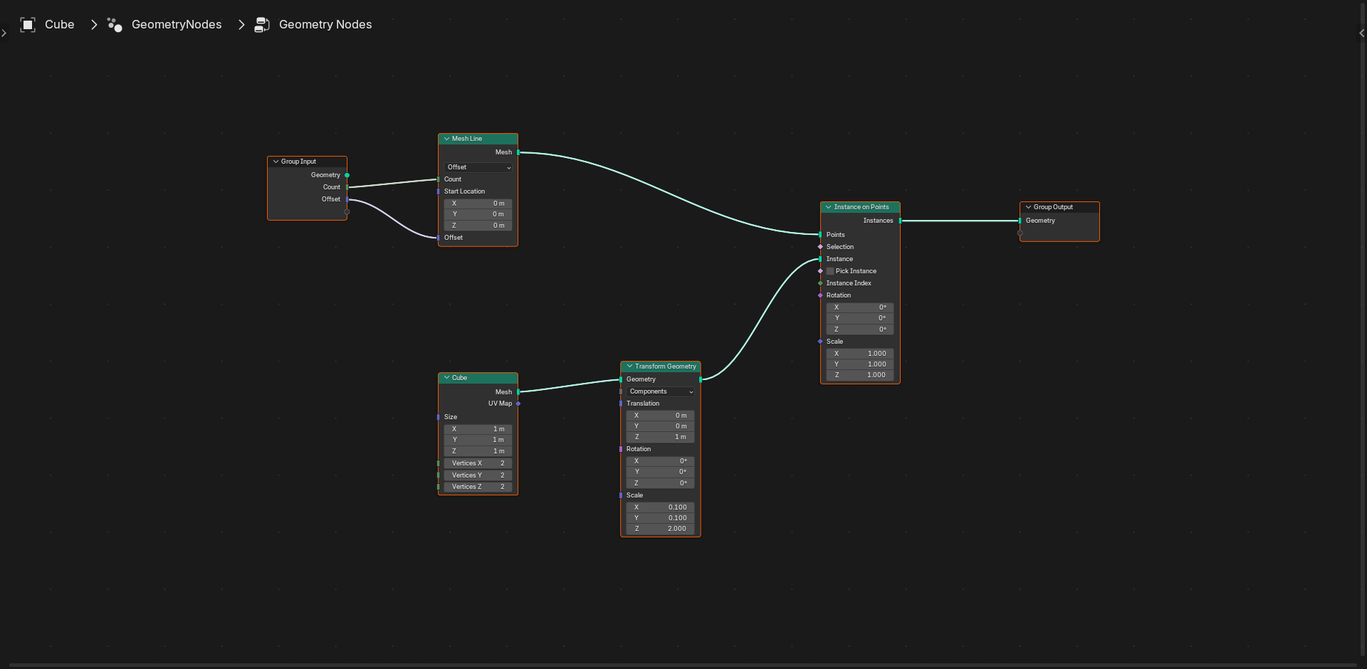
Shift + A> Instances > Instance on Points- Place it to the right of Mesh Line
2. Connect Nodes:
First Connection: Points
- Click and drag from Mesh Line's "Mesh" output (green socket on right)
- Drag to Instance on Points' "Points" input (top green socket on left)
- Line appears connecting them
- This says: "Use these points as instance locations"
Second Connection: What to Instance
- Click and drag from Group Input's "Geometry" output (green socket)
- Drag to Instance on Points' "Instance" input (second green socket on left)
- This says: "Copy the input cube to each point"
Third Connection: Output Result
- Click and drag from Instance on Points' "Instances" output (green socket on right)
- Drag to Group Output's "Geometry" input (green socket)
- This displays the result in viewport
- Note: This replaces the direct Input→Output connection (that's okay!)
Original Cube] --> B[Instance on Points
Instance Socket] C[Mesh Line
10 Points] --> D[Instance on Points
Points Socket] B --> E[Instance on Points] D --> E E --> F[Group Output
Display Result] style A fill:#4CAF50,stroke:#333,stroke-width:2px,color:#fff style C fill:#2196F3,stroke:#333,stroke-width:2px,color:#fff style F fill:#3a3a3a,stroke:#333,stroke-width:2px,color:#fff
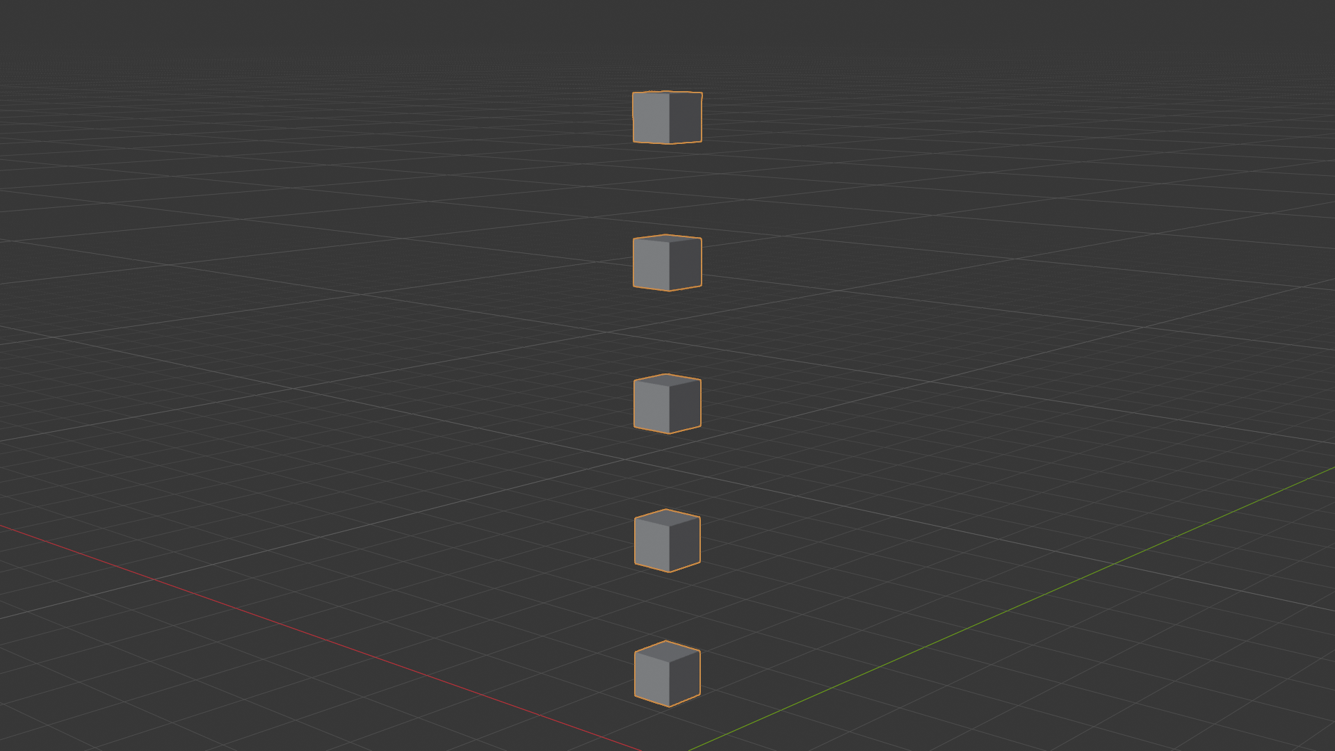
🎉 First Result!
Look at your viewport now:
- You should see 10 cubes stacked vertically!
- Each cube positioned at a point from Mesh Line
- Spaced 2.5 units apart
- All procedural—no manual duplication!
If you don't see cubes: Check all three connections are correct. Green lines should form continuous path from Input to Output.
Step 5: Make It Interactive
💡 Add Controllable Parameters
Problem: Count and spacing are fixed. To change them, we'd need to modify node values directly. Not very flexible!
Solution: Expose parameters to Group Input. This creates sliders in modifier panel that control node values. User-friendly and powerful!
✅ Expose Count Parameter
1. Find the Count Field:
- On Mesh Line node
- "Count" number field (currently says 10)
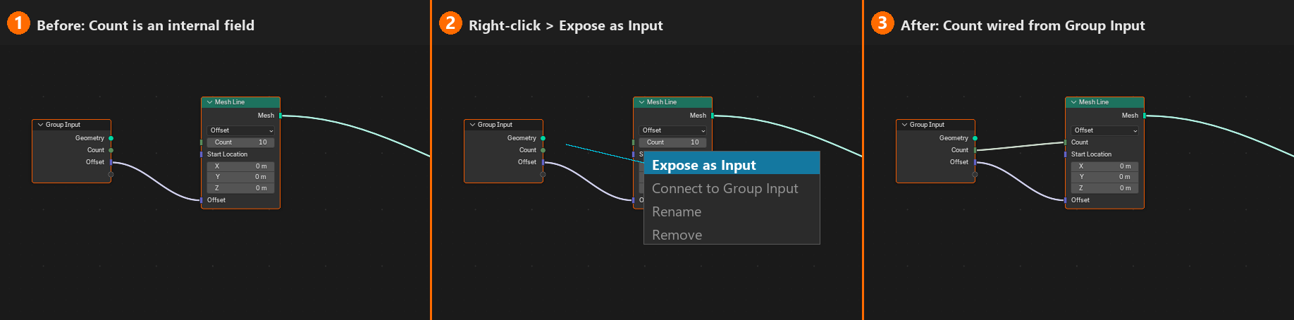
2. Make It a Socket:
- Hover over "Count" label (not the value)
- Right-click on the label
- Context menu appears
- Select "Expose as Input" (or "Make Socket")
3. What Happened:
- "Count" field becomes a socket (gray circle appears on left side of node)
- Group Input node grows: New "Count" output socket appears!
- Automatically connected: Group Input "Count" → Mesh Line "Count"
4. Test It:
- Look at right side panel (Modifier Properties)
- Geometry Nodes modifier should show "Count" slider
- Drag slider: Number of cubes changes in real-time!
- Try: 5 cubes... 20 cubes... 50 cubes!
✅ Expose Offset Parameter
Same Process for Spacing:
- Find "Offset" field on Mesh Line node
- Right-click on "Offset" label
- Select "Expose as Input"
- Result: Group Input gains "Offset" socket (purple, it's a Vector)
Test Spacing:
- Modifier panel now has "Offset" controls (X, Y, Z)
- Change Z value:
1.0(tight stack) or5.0(spread out) - Cubes adjust spacing instantly
💭 Understanding Exposed Inputs: When you expose a parameter, you're saying "this value should be controllable from outside the node tree." It's like creating a dial on a machine. The node tree becomes a tool with adjustable settings. This is how procedural systems become user-friendly—hide complexity inside, expose controls outside!
Step 6: Realize Instances (Optional)
🔄 Convert Instances to Real Geometry
Current State: Instances
- Cubes are instances (efficient, lightweight)
- All reference same source geometry
- Can't individually edit (they're all the same cube)
If You Need Real Geometry:
- Add node:
Shift + A> Instances > Realize Instances - Insert BEFORE Group Output:
- Delete connection: Instance on Points → Group Output
- Connect: Instance on Points → Realize Instances → Group Output
- Result: Instances converted to actual mesh copies
When to Realize:
- Need to apply modifiers to individual copies
- Want to edit geometry per instance
- Exporting to formats that don't support instances
When NOT to Realize:
- High instance counts (thousands) - realized geometry gets heavy
- Want to maintain efficiency
- Instances work fine for your needs
⚠️ Performance Note
Instances vs. Realized:
- 10 instances: ~No difference
- 1,000 instances: Still fast! Realized = slow
- 10,000 instances: Instances smooth, realized = lag
- Rule: Keep as instances unless you have specific reason to realize
Experiment Time!
🎨 Try These Variations
1. Different Shapes:
- Replace Mesh Cube with different primitive:
- Add: Mesh > Primitives > UV Sphere
- Connect: UV Sphere → Instance on Points "Instance" socket
- Result: Stack of spheres instead!
2. Change Direction:
- Modify Offset in modifier panel:
X: 2.5, Y: 0, Z: 0→ Horizontal stackX: 1.5, Y: 1.5, Z: 1.5→ Diagonal!
3. Add Randomness:
- Add: Utilities > Random Value (between Instance on Points and output)
- Connect to scale or rotation
- Each cube slightly different!
4. Circular Pattern:
- Replace Mesh Line with: Mesh Circle (keep "Count" mode)
- Connect: Mesh Circle → Instance on Points
- Result: Cubes arranged in circle!
Understanding What You Built
💡 Key Concepts Demonstrated
1. Node Workflow:
- Add nodes → Configure parameters → Connect sockets → See results
- Iterative: Try, observe, adjust, repeat
- Non-destructive: Change anything anytime
2. Separation of Concerns:
- What: Instance (the cube we're copying)
- Where: Points (locations for copies)
- How: Instance on Points (the copying mechanism)
- Each node has single, clear purpose
3. Data Types Matter:
- Geometry (green) flows through main path
- Points are special geometry type (positions without mesh)
- Instance on Points needs BOTH geometry types (points + instance)
4. User Interface:
- Exposed inputs = modifier panel controls
- Non-exposed values = node tree only
- Choose what end-users should control
5. Real-Time Feedback:
- Every change updates viewport immediately
- No "apply" or "execute" needed
- Encourages experimentation
Common Issues and Solutions
⚠️ Troubleshooting Your First Node Tree
Problem: Can't See Any Cubes
- Check: All nodes connected? Trace path from Input to Output
- Check: Group Output has green connection? Nothing outputs = nothing visible
- Check: Cube is selected in viewport?
- Fix: Verify each connection, remake if needed
Problem: Only See Original Cube
- Likely cause: Direct Input → Output connection still exists
- Fix: Delete old connection, ensure Instance on Points connects to Output
Problem: Cubes Overlapping
- Cause: Offset too small for cube size
- Fix: Increase Z offset (try 2.5 or 3.0)
Problem: Cubes in Wrong Direction
- Cause: Offset vector pointed differently
- Fix: Adjust X, Y, Z values in Offset
- Vertical:
Z = 2.5,X = Y = 0 - Horizontal:
X = 2.5,Y = Z = 0
- Vertical:
Problem: Can't Find "Expose as Input"
- Check: Right-clicking on parameter label, not value field
- Alternative: Drag from Group Input output socket to parameter
Problem: Viewport Lagging
- Cause: Too many instances (especially if realized)
- Fix: Reduce count slider
- Fix: Keep as instances (don't add Realize Instances node)
Next Steps and Challenges
✅ Extend Your Project
Challenge 1: Add Rotation
- Add "Rotate Instances" node after Instance on Points
- Set rotation:
Z = 15° - Each cube rotates slightly—creates spiral effect!
Challenge 2: Scale Variation
- Add "Scale Instances" node
- Gradually scale down: Bottom large, top small (pyramidal stack)
- Hint: Use "Index" from Mesh Line for per-point variation
Challenge 3: Multiple Shapes
- Create two instance paths: One with cubes, one with spheres
- Use "Join Geometry" to combine
- Result: Alternating cubes and spheres (advanced!)
Challenge 4: Material Variation
- Add "Set Material" node
- Create multiple materials
- Use "Random Value" to assign different materials to instances
- Colorful stack!
💭 Reflection: You've just built your first procedural system! Think about what this means: One setup, infinite variations. Change parameters, swap geometry, add nodes—all without starting over. This is the power of procedural modeling. What you learned in this simple stack applies to forests, buildings, particles, crowds, and more. The principles are the same; only the complexity scales. You're no longer just a modeler—you're a system designer!
🎯 First Node Tree Complete!
- You learned: Complete Geometry Nodes workflow from empty editor to working system
- You practiced: Adding nodes, making connections, exposing parameters
- You understand: Instancing, point distribution, data flow, and real-time updates
- You created: A procedural system with interactive controls
This foundation supports everything else you'll build in Geometry Nodes!
📚 Essential Beginner Nodes Reference
Now that you've built your first node tree, let's expand your toolkit! There are hundreds of Geometry Nodes, but you don't need to know them all to create amazing things. In this section, we'll cover the essential nodes that you'll use again and again—the "greatest hits" of Geometry Nodes. Think of these as your starter pack: master these nodes, and you'll be able to build 80% of what you'll want to create. We'll organize them by category and show you exactly when and why to use each one. Let's build your node vocabulary!
🎯 Node Categories
We'll cover:
- Primitives: Building blocks (cubes, spheres, grids)
- Geometry Operations: Transform, join, delete, duplicate
- Instances: Efficient copying and placement
- Attributes: Reading and writing data
- Math & Utilities: Numbers, vectors, conversions
- Curves: Lines, circles, paths
Focus: Practical understanding over memorization!
Primitive Generators
🧊 Mesh Primitives (Add > Mesh > Primitives)
These nodes CREATE new geometry from scratch. They ignore input geometry and generate fresh meshes.
Mesh Cube
- What it does: Creates a cube mesh
- Parameters:
- Size: Overall dimensions (uniform or per-axis)
- Vertices X/Y/Z: Subdivisions per axis
- Use when: Need basic box shape, building, room, container
- Output: Green geometry socket (the cube mesh)
UV Sphere
- What it does: Creates a sphere with UV-friendly topology
- Parameters:
- Segments: Horizontal rings
- Rings: Vertical segments
- Radius: Size
- Use when: Planets, balls, bubbles, round objects
- Note: Higher segments/rings = smoother but heavier
Ico Sphere
- What it does: Creates sphere from icosahedron (more even topology)
- Parameters:
- Subdivisions: Detail level (each level quadruples faces)
- Radius: Size
- Use when: Need more uniform sphere, subdividing sphere, geodesic patterns
- Warning: Subdivision 4+ = very heavy (thousands of faces)
Cylinder
- What it does: Creates cylinder mesh
- Parameters:
- Vertices: Sides (6 = hexagon, 32 = smooth cylinder)
- Radius: Width at top and bottom (different = cone/frustum)
- Depth: Height
- Fill Type: None/NGon/Triangles (cap options)
- Use when: Pillars, tubes, pipes, tree trunks
Cone
- What it does: Creates cone mesh (cylinder with zero top radius)
- Parameters: Similar to cylinder
- Use when: Pointed objects, arrows, mountain, party hat
Grid
- What it does: Creates flat grid of faces
- Parameters:
- Size X/Y: Dimensions
- Vertices X/Y: Subdivisions (resolution)
- Use when: Ground plane, terrain base, cloth simulation start
- Pro tip: High vertex count grid = great for displacement/noise
💡 Curve Primitives (Add > Curve > Primitives)
Curves are special: They're paths/lines, not solid geometry (until converted to mesh).
Curve Line
- What it does: Creates straight line curve
- Modes:
- Points: Line between two points
- Direction: Start point + direction vector + length
- Use when: Straight edges, paths, extrusion rails
Curve Circle
- What it does: Creates circular curve
- Parameters: Radius, resolution (points on circle)
- Use when: Circular paths, rings, orbits, wheels
Mesh Line
- What it does: Creates line of POINTS (not connected)
- Modes:
- Count: Specific number of points
- Resolution: Points based on length/spacing
- Use when: Instance locations, particle positions (most common!)
- Remember: This is what we used in first project!
Geometry Operations
✅ Transform and Modify (Add > Geometry)
Transform Geometry
- What it does: Moves, rotates, scales entire geometry
- Inputs:
- Geometry (what to transform)
- Translation (move)
- Rotation (rotate in Euler angles)
- Scale (resize)
- Use when: Repositioning generated geometry, offsetting, simple transformations
- Note: Affects ALL geometry equally (not per-point)
Set Position
- What it does: Moves individual points/vertices
- Inputs:
- Geometry (mesh to modify)
- Selection (which points to affect - optional mask)
- Position (new positions - Vector)
- Offset (relative movement - adds to current position)
- Use when: Per-vertex modifications, deformations, displacement
- Pro tip: Use with noise to create organic deformations
Join Geometry
- What it does: Combines multiple geometry inputs into one
- Inputs: Multiple geometry sockets (expandable with + button)
- Use when: Merging separate branches, combining primitives, adding to input
- Critical node: Most trees need this somewhere!
Delete Geometry
- What it does: Removes selected parts of geometry
- Inputs:
- Geometry (what to delete from)
- Selection (which parts to delete - boolean mask)
- Domain: Points, Edges, Faces (what type to delete)
- Use when: Removing unwanted parts, creating holes, selective pruning
Duplicate Elements
- What it does: Duplicates selected geometry elements
- Inputs:
- Geometry
- Selection (what to duplicate)
- Amount (how many copies)
- Use when: Creating repeating patterns, multiplying faces
Instance Operations
📦 Working with Instances (Add > Instances)
Instance on Points
- What it does: Places instances at point locations
- Inputs:
- Points: Where to place instances (geometry with points)
- Instance: What to copy
- Selection: Which points to use (optional)
- Pick Instance: Choose from multiple instance options
- Rotation/Scale: Per-instance transformation
- Use when: Scattering objects, placing copies, distribution systems
- Most used node: Core of most procedural systems!
Realize Instances
- What it does: Converts instances to real geometry
- Input: Geometry (with instances)
- Output: Geometry (instances converted to meshes)
- Use when: Need to modify individual copies, apply modifiers, export
- Warning: Heavy operation with many instances!
Rotate Instances
- What it does: Rotates instances (without realizing them)
- Inputs:
- Instances
- Selection: Which instances to rotate
- Rotation: Euler angles
- Use when: Randomizing rotations, aligning instances, orientation control
- Efficient: Modifies instance data, not geometry
Scale Instances
- What it does: Scales instances (without realizing)
- Inputs:
- Instances
- Selection: Which instances
- Scale: Per-axis or uniform
- Use when: Size variation, randomization, progressive scaling
Translate Instances
- What it does: Moves instances from their points
- Use when: Offsetting from exact point locations, jitter, displacement
Rotate/Scale/Translate] D -->|Yes| F[Realize Instances
Convert to Mesh] E --> G[Output
Efficient] F --> H[Output
Editable but Heavy] style B fill:#3a3a3a,stroke:#333,stroke-width:2px,color:#fff style D fill:#ffc107,stroke:#333,stroke-width:2px
Attribute Operations
💡 Reading and Writing Data (Add > Attribute)
Understanding Attributes:
- Attributes = data stored per point/edge/face
- Examples: Position, Normal, Color, Custom values
- Think of them as spreadsheet columns (each point/face = row)
Store Named Attribute
- What it does: Saves data to geometry for later use
- Inputs:
- Geometry
- Name: Attribute identifier (text)
- Value: Data to store (any type)
- Use when: Need to remember data, pass info between nodes, mark geometry
- Example: Store random values, mark selected faces, save IDs
Named Attribute (Read)
- What it does: Retrieves stored attribute data
- Input: Name (attribute to read)
- Output: Attribute values (color-coded by type)
- Use when: Reading previously stored data, accessing built-in attributes
Built-in Attributes (Always Available):
- position: Point locations (Vector)
- normal: Surface direction (Vector)
- id: Point/face index (Integer)
- material_index: Material slot (Integer)
- Access these without storing—they exist automatically!
Capture Attribute
- What it does: Saves current state of attribute for later comparison
- Use when: Need "before and after" comparisons, measuring change
- Example: Capture original position, then measure displacement amount
Math and Utilities
✅ Number Crunching (Add > Utilities)
Math Node
- What it does: Performs math operations on floats (single numbers)
- Operations:
- Basic: Add, Subtract, Multiply, Divide
- Functions: Power, Square Root, Absolute, Round
- Comparison: Less Than, Greater Than, Compare
- Trigonometry: Sine, Cosine, Tangent
- Many more! (dropdown menu has 30+ options)
- Use when: Calculations, value manipulation, formulas
Vector Math Node
- What it does: Math operations on vectors (X,Y,Z triplets)
- Operations:
- Add, Subtract, Multiply, Divide (per-component)
- Dot Product, Cross Product
- Normalize (make length = 1)
- Length, Distance
- Use when: Position calculations, directions, scaling vectors
Map Range
- What it does: Remaps values from one range to another
- Example: Convert 0-10 range to 0-100 range
- Inputs:
- Value: Input to remap
- From Min/Max: Original range
- To Min/Max: Target range
- Use when: Scaling parameters, normalizing values, adjusting ranges
- Pro tip: Essential for making procedural systems flexible!
Compare (Math Node variant)
- What it does: Compares values, outputs boolean (true/false)
- Operations: Less Than, Greater Than, Equal, Not Equal
- Use when: Creating selections, conditional logic, filtering
- Output: Boolean (white socket) - use for Selection inputs!
Random Value
- What it does: Generates random numbers or vectors
- Types: Float, Integer, Vector, Boolean
- Parameters:
- Min/Max: Range of random values
- ID: Seed (same ID = same "random" result)
- Seed: Global randomization offset
- Use when: Variation, scatter, natural randomness
- Pro tip: Use Index as ID for per-point randomness!
🔄 Type Conversions (Add > Utilities > Convert)
Combine XYZ
- What it does: Combines three floats into vector
- Inputs: X, Y, Z (gray sockets)
- Output: Vector (purple socket)
- Use when: Building vectors from separate values
Separate XYZ
- What it does: Splits vector into three floats
- Input: Vector (purple socket)
- Outputs: X, Y, Z (gray sockets)
- Use when: Need individual components, isolating one axis
Float to Integer
- What it does: Converts float to integer
- Modes: Round, Floor, Ceiling, Truncate
- Use when: Index calculations, counting, discrete values
Index and ID
💡 Tracking Elements (Add > Input)
Index Node
- What it does: Outputs each element's index number
- Output: Integer (0, 1, 2, 3...)
- Domain-dependent: Changes based on context
- Point domain: 0 = first point, 1 = second point, etc.
- Face domain: 0 = first face, 1 = second face, etc.
- Use when:
- Creating gradients (index → color)
- Per-element variation (index → random seed)
- Selecting every Nth element (index modulo N)
- Progressive effects (first different from last)
- Common pattern: Index → Random Value ID (unique randomness per element)
ID Node
- What it does: Reads stored ID attribute (if it exists)
- Difference from Index:
- Index: Automatic, sequential (0, 1, 2...)
- ID: Custom, stored attribute (can be any values)
- Use when: Tracking specific elements after modifications
Quick Reference Tables
📊 Node Selection Guide
| Task | Use This Node | Why |
|---|---|---|
| Create starting geometry | Mesh Cube/Sphere/Grid | Primitives generate fresh geometry |
| Copy object many times | Instance on Points | Most efficient duplication method |
| Combine separate objects | Join Geometry | Merges multiple geometry streams |
| Move entire object | Transform Geometry | Uniform transformation |
| Move individual vertices | Set Position | Per-point control |
| Add randomness | Random Value | Generates varied values |
| Create point line | Mesh Line | Perfect for instance locations |
| Remove parts | Delete Geometry | Selective removal |
| Make instances editable | Realize Instances | Converts to real geometry |
| Do math calculations | Math/Vector Math | Numerical operations |
| Change value ranges | Map Range | Remap min/max |
| Build vectors | Combine XYZ | Three floats → vector |
| Per-element variation | Index | Sequential numbering |
✅ Socket Color Cheat Sheet
| Color | Data Type | Example Values | Common Uses |
|---|---|---|---|
| Green | Geometry | Meshes, curves, instances | Main data flow |
| Gray | Float | 0.5, -2.7, 100.0 | Numbers, measurements |
| Blue | Integer | 0, 5, -3, 42 | Counts, indices |
| Purple | Vector | (1.0, 2.5, -0.5) | Positions, directions |
| White | Boolean | True/False | Selections, masks |
| Yellow | Color | RGBA (0-1 per channel) | Vertex colors, materials |
💭 Building Your Mental Library: You don't need to memorize every node—that's what the Add menu is for! What you DO need is to understand categories: "When I need to create geometry, look in Mesh/Primitives. When I need to scatter, use Instance on Points. When I need math, use Math nodes." With practice, you'll know the 10-15 nodes you use constantly, and you'll look up the rest as needed. That's how professionals work too!
🎯 Essential Nodes Summary
Your Core Toolkit:
- Primitives: Cube, Sphere, Grid (starting shapes)
- Points: Mesh Line, Curve Circle (instance locations)
- Instances: Instance on Points, Realize Instances (efficient copying)
- Transforms: Transform Geometry, Set Position (movement)
- Combine: Join Geometry (merge branches)
- Math: Math, Vector Math, Map Range, Random Value (calculations)
- Conversion: Combine/Separate XYZ (type matching)
- Tracking: Index (per-element identification)
Master these, and you're ready for 90% of projects!
🎨 Practical Project: Procedural Fence
Time to put everything together! You've learned the interface, understood the concepts, explored essential nodes, and built your first simple stack. Now let's create something more practical and impressive: a fully procedural fence system. This project will teach you how to combine multiple techniques—curves, instancing, transformations, and parameters—into a real-world asset. By the end, you'll have a fence that can bend around any path, adjust its height, change post spacing, and swap styles instantly. This is the kind of procedural system professionals use in production. Let's build it!
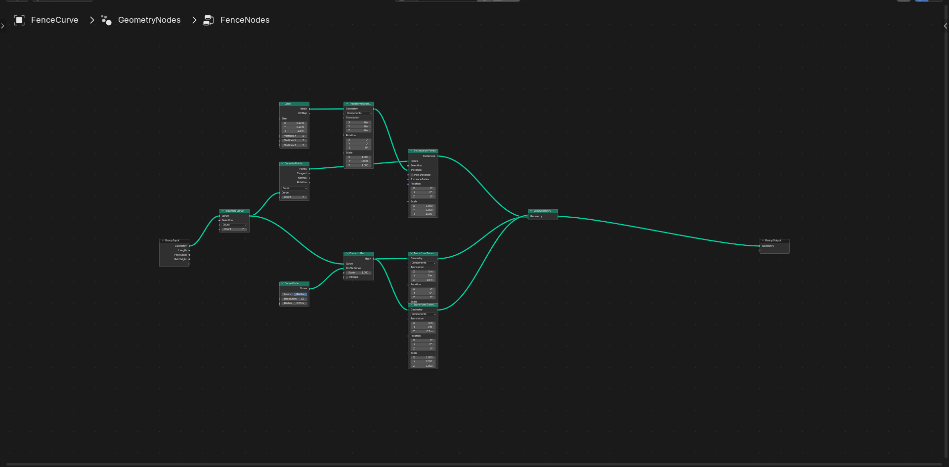
🎯 Project Overview: Procedural Fence System
What We're Building:
- Fence posts distributed along a curved path
- Horizontal rails connecting the posts
- Fully adjustable parameters (height, spacing, rail count)
- Works with any curve shape (straight, curved, complex paths)
- One click to change entire fence style
Skills Applied:
- Curve-based distribution
- Multiple instance types
- Transform control
- Joining geometry streams
- Parameter exposure and organization
Time: 20-30 minutes • Difficulty: Intermediate
Phase 1: Setup and Planning
✅ Scene Preparation
1. Create Base Curve:
- Delete default cube (
X+ confirm) Shift + A> Curve > Bezier (or Path)- This curve will define fence path
- Optional: Enter Edit mode (
Tab), move control points to create interesting path - Tip: Keep it simple for now (straight or gentle curve)
2. Add Geometry Nodes Modifier:
- Select curve
- Switch to Geometry Nodes workspace
- Click "New" in Geometry Node Editor
- Default Group Input → Group Output appears
3. Understand the Goal:
- Input: Curve path
- Process: Sample points along curve, place posts, add rails
- Output: Complete fence following curve
Along Curve] B --> C[Place Fence Posts
at Points] B --> D[Create Horizontal
Rails] C --> E[Join Geometry] D --> E E --> F[Output
Complete Fence] style A fill:#4CAF50,stroke:#333,stroke-width:2px,color:#fff style F fill:#3a3a3a,stroke:#333,stroke-width:2px,color:#fff
Phase 2: Create Fence Post Template
💡 Build the Post
Why Start Here: We need a post to instance. Build it first, then distribute copies.
1. Add Mesh Cube Node:
Shift + A> Mesh > Primitives > Mesh Cube- Place it anywhere in editor (we'll organize later)
- This will become our fence post
2. Scale Post to Proper Proportions:
- Add:
Shift + A> Geometry > Transform Geometry - Connect: Mesh Cube → Transform Geometry
- Set Transform Geometry parameters:
- Scale:
X: 0.1, Y: 0.1, Z: 2.0 - Makes it thin (0.1m × 0.1m) and tall (2m high)
- Scale:
- Result: Cube becomes post-shaped
3. Position Post Correctly:
- Still in Transform Geometry node
- Translation:
X: 0, Y: 0, Z: 1.0 - This moves post up so bottom sits at Z=0 (ground level)
- Why? Posts will be placed at curve points (which are at ground level)
Don't connect to output yet! This is just a template for instancing.
✅ Quick Test (Optional)
Want to See the Post?
- Temporarily connect: Transform Geometry → Group Output
- You should see single tall, thin post in viewport
- Looks good? Delete that connection (we'll instance it next)
- This temp connection helps verify post shape
Phase 3: Sample Points Along Curve
📍 Distribute Post Locations
The Plan: Sample points along input curve at regular intervals. These points become post positions.
1. Add Resample Curve Node:
Shift + A> Curve > Operations > Resample Curve- This node adds points to curve at even spacing
2. Connect Input Curve:
- Connect: Group Input "Curve" → Resample Curve "Curve"
- This processes the input curve (the Bezier we created)
3. Configure Resample Settings:
- Mode: Set to "Length" (dropdown at top of node)
- Length: Set to
2.0(meters between points) - This creates point every 2 meters along curve
- 2 meters = good fence post spacing
4. Convert Curve to Points:
Shift + A> Curve > Operations > Curve to Points- Connect: Resample Curve → Curve to Points
- This extracts point positions from curve (ready for instancing)
What We Have Now:
- Points distributed evenly along curve
- Spacing controlled by Resample "Length" parameter
- These points will host our post instances
Phase 4: Instance Posts on Points
✅ Place the Posts
1. Add Instance on Points Node:
Shift + A> Instances > Instance on Points- This is our workhorse—places copies at locations
2. Connect Points and Post:
- Points input: Curve to Points → Instance on Points "Points"
- Instance input: Transform Geometry (the post) → Instance on Points "Instance"
- This says: "Copy this post to each curve point"
3. Connect to Output (First Result!):
- Connect: Instance on Points → Group Output "Geometry"
- Look at viewport! You should see posts along your curve!
- If curve is straight: Posts in line
- If curve bends: Posts follow the path
⚠️ Troubleshooting Post Placement
Don't See Posts?
- Check all connections: Group Input → Resample → Curve to Points → Instance on Points → Output
- Verify post is connected to "Instance" socket
- Try increasing Resample "Length" (maybe curve too short for multiple posts)
Posts Wrong Size?
- Check Transform Geometry scale: Should be (0.1, 0.1, 2.0)
- Adjust as needed for your scene scale
Posts Not at Ground Level?
- Check Transform Geometry translation Z: Should be 1.0
- Adjusts based on post height (half of Z-scale)
Phase 5: Add Horizontal Rails
💡 Create Rail System
The Challenge: Rails need to follow curve but be horizontal bars. We'll use the curve itself as rail geometry!
1. Add Curve to Mesh Node:
Shift + A> Curve > Operations > Curve to Mesh- This converts curve to mesh (gives it thickness)
2. Create Rail Profile:
Shift + A> Curve > Primitives > Curve Circle- Set Radius:
0.03(thin rail, 3cm diameter) - This circle defines rail cross-section
3. Connect Rail Components:
- Connect: Resample Curve → Curve to Mesh "Curve"
- Uses same resampled curve (follows fence path)
- Connect: Curve Circle → Curve to Mesh "Profile Curve"
- Sweeps circle along path, creating cylindrical rail
4. Position Rail at Correct Height:
- Add: Transform Geometry node
- Connect: Curve to Mesh → Transform Geometry
- Translation Z:
1.5(raises rail to upper part of post) - Now rail floats at fence height
✅ Add Second Rail (Bottom)
Duplicate the Rail Setup:
- Select Transform Geometry node (the one for rail)
Shift + Dto duplicate- Move duplicate below original
- Change Translation Z:
0.7(lower rail position) - Connect: Curve to Mesh → This new Transform Geometry
- Same rail mesh, different height
Pro Tip: You can add 3, 4, or more rails by duplicating again with different Z translations!
Phase 6: Combine All Elements
🔗 Join Everything Together
Current State: We have three separate geometry branches:
- Posts (Instance on Points)
- Top rail (Transform Geometry #1)
- Bottom rail (Transform Geometry #2)
Problem: Only one connects to output. We need all three visible!
Solution: Join Geometry Node
- Add:
Shift + A> Geometry > Join Geometry - Place it before Group Output
- Delete existing connection to Group Output
- Connect THREE inputs:
- Instance on Points → Join Geometry
- Transform Geometry #1 (top rail) → Join Geometry
- Transform Geometry #2 (bottom rail) → Join Geometry
- Connect: Join Geometry → Group Output
Result:
- Complete fence in viewport!
- Posts standing vertically
- Two horizontal rails connecting them
- Follows curve path perfectly
Make Post Shape] F --> G[Instance on Points] C --> G H[Curve Circle
Rail Profile] --> D D --> I[Transform
Top Rail Z=1.5] D --> J[Transform
Bottom Rail Z=0.7] G --> K[Join Geometry] I --> K J --> K K --> L[Group Output] style A fill:#4CAF50,stroke:#333,stroke-width:2px,color:#fff style K fill:#2196F3,stroke:#333,stroke-width:2px,color:#fff style L fill:#3a3a3a,stroke:#333,stroke-width:2px,color:#fff
Phase 7: Make It Adjustable
🎛️ Expose Key Parameters
Make your fence interactive! Users should control these values without opening node editor.
✅ Parameters to Expose
1. Post Spacing (Resample Length):
- Find Resample Curve node
- Right-click "Length" label
- Select "Expose as Input"
- Rename in Modifier Panel: "Post Spacing"
- More user-friendly than "Length"
- Test: Adjust slider to see posts spread out or bunch up
2. Post Height (Transform Z Scale):
- Find Transform Geometry (post shaping node)
- Right-click "Scale" label
- Expose as input
- Rename: "Post Scale"
- Note: Exposes all three axes (X, Y, Z)
- Z controls height
- X and Y control thickness
3. Rail Radius (Curve Circle):
- Find Curve Circle node
- Right-click "Radius" label
- Expose as input
- Rename: "Rail Thickness"
- Makes rails thicker or thinner
4. Rail Heights (Optional but Useful):
- Expose Translation Z on both rail Transform Geometry nodes
- Rename: "Top Rail Height" and "Bottom Rail Height"
- Allows custom rail positioning
💡 Organize Your Inputs
Group Input Node Gets Messy: Many outputs now! Organize them:
In Modifier Panel:
- You'll see all exposed parameters
- Drag to reorder (most important at top)
- Good order:
- Post Spacing (most frequently adjusted)
- Post Scale
- Top Rail Height
- Bottom Rail Height
- Rail Thickness
Add Min/Max Limits:
- In modifier panel, click small icon next to parameter
- Set sensible ranges:
- Post Spacing: Min 0.5, Max 5.0
- Rail Thickness: Min 0.01, Max 0.1
- Prevents users from entering broken values
Phase 8: Enhancements and Polish
✅ Optional Improvements
Enhancement 1: Realize for Editing
- Add Realize Instances before Join Geometry (on post branch)
- Allows applying materials differently to posts
- Makes instances editable if needed
- Trade-off: Slightly heavier, but more flexible
Enhancement 2: Cap Options
- Add Mesh Boolean or other cap geometry to post tops
- Creates decorative finials (ball tops, points, etc.)
- Just join another primitive to post before instancing
Enhancement 3: Variable Post Heights
- Add Random Value node
- Connect to post scale's Z component
- Creates organic variation (not all posts same height)
Enhancement 4: Add Gate Opening
- Use Delete Geometry on specific point indices
- Compare Index to target range
- Removes posts in gate area
- Advanced: Replace with different geometry (gate frame)
Enhancement 5: Materials
- Add Set Material nodes for posts and rails
- Apply different materials (wood, metal, painted)
- Can expose material selection to modifier panel
Testing Your Fence
🧪 Verify Flexibility
Test 1: Modify Curve Shape
- Tab into Edit mode on curve
- Move control points
- Tab back to Object mode
- Result: Fence updates automatically to follow new path!
Test 2: Adjust Parameters
- Change Post Spacing: 1.0 (tight) to 4.0 (spread out)
- Modify Post Scale Z: 1.0 (short) to 3.0 (tall)
- Adjust Rail Heights: Create different rail patterns
- Everything updates in real-time!
Test 3: Complex Curves
- Create S-curve
- Add sharp corners
- Make circular path
- Fence handles all shapes gracefully
Test 4: Duplicate and Vary
- Duplicate your fence object (
Shift + D) - Change parameters on copy
- Create different fence styles (tall privacy, short picket, wide ranch)
- All from same node setup!
💭 The Power of Procedural Systems: Think about what you just built. Without Geometry Nodes, creating a fence along a curved path would require: modeling each post, manually positioning them, creating rail geometry, aligning rails, adjusting everything if path changes. Hours of work. With Geometry Nodes: Draw curve, adjust parameters, done. Minutes. And you can reuse this system forever, on any project, with any path. This is why procedural modeling is revolutionary—it transforms modeling from tedious repetition into intelligent system design!
🎯 Project Complete!
What You Accomplished:
- Built: Complete procedural fence system from scratch
- Applied: Curves, instancing, transforms, joining, parameters
- Created: Reusable asset that adapts to any situation
- Learned: Real production workflow for procedural modeling
Skills Gained:
- Multi-component system design
- Curve-based distribution
- Parameter organization and exposure
- Geometry stream management
- Testing and refinement workflow
You're now a Geometry Nodes practitioner!
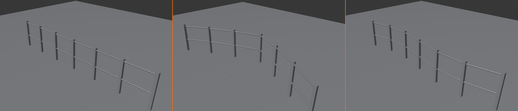
✅ Challenge Extensions
Master the Fence: Try these challenges to deepen your understanding:
Challenge 1: Picket Fence Style
- Replace post cube with pointed-top geometry
- Reduce post spacing to 0.3m (tight pickets)
- Adjust rail positions to proper picket fence heights
Challenge 2: Chain Link Fence
- Keep posts
- Replace rails with subdivided grid (Mesh > Grid)
- Apply Wave or Displacement modifier for chain link texture
- Add wire material
Challenge 3: Stone Wall
- Replace posts with stone block instances
- Add Random Value for size variation
- Stack multiple layers (different heights)
- Remove rails or keep as mortar lines
Challenge 4: Add Corner Posts
- Detect curve direction changes
- Place larger posts at corners
- Hint: Use Curve Tangent attribute
Challenge 5: Parametric Gate
- Expose "Gate Start" and "Gate End" parameters
- Use Compare node on Index
- Delete posts in gate range
- Add gate geometry in that space
🔧 Troubleshooting and Common Issues
Even experienced users encounter problems in Geometry Nodes—it's part of the learning process! The difference between frustration and growth is knowing how to diagnose and fix issues. In this section, we'll cover the most common problems beginners face, explain why they happen, and show you exactly how to solve them. Think of this as your emergency toolkit: when something goes wrong, come back here. We'll also teach you debugging strategies that help you solve problems independently. Let's turn those confusing errors into learning opportunities!
🎯 Debugging Mindset
The Three Questions:
- What do I expect to see? (Your intended result)
- What do I actually see? (The current output)
- Where is the difference introduced? (Which node causes the mismatch)
Master these questions, and you can debug anything!
Visual Issues
⚠️ Problem: Geometry Disappears
Symptom: Object vanishes when adding Geometry Nodes modifier, or disappears after connecting nodes.
Common Causes and Fixes:
Cause 1: Nothing Connected to Group Output
- Why it happens: No geometry reaching output = nothing to display
- How to identify: Group Output's "Geometry" input has no connection
- Fix:
- Trace backwards from Group Output
- Find your final processing node
- Connect it to Group Output "Geometry"
- Remember: SOMETHING must connect to output!
Cause 2: Geometry Replaced by Generator
- Why it happens: Generator nodes (Cube, Sphere) ignore input, create new geometry
- Example: Cube → Output (cube replaces input object)
- Fix:
- If you want both: Use Join Geometry
Group Input → → Join Geometry → Output Cube → - If you want only new geometry: This is correct behavior!
- If you want both: Use Join Geometry
Cause 3: Delete Geometry Removed Everything
- Why it happens: Selection mask deletes all geometry
- How to identify: Check Delete Geometry's "Selection" input
- Fix:
- Verify selection is correct (should be boolean field)
- If no selection connected, ALL geometry deleted
- Use Compare or other nodes to create proper mask
Cause 4: Scale = 0
- Why it happens: Transform or Scale node set to zero
- Fix: Check Transform Geometry and Scale Instances for zero values
⚠️ Problem: Instances Invisible or Wrong
Symptom: Instance on Points doesn't show copies, or shows wrong geometry.
Cause 1: Nothing Connected to "Instance" Socket
- Fix: Connect geometry to Instance on Points "Instance" input
- This is WHAT to copy (the template)
Cause 2: No Points Provided
- Fix: Connect point geometry to "Points" input
- This is WHERE to place copies (the locations)
- Common mistake: Connecting mesh instead of points
- Use Mesh to Points or Curve to Points to extract point locations
Cause 3: Instances Too Small or Large
- Symptom: Instances exist but wrong size
- Fix:
- Check Scale input on Instance on Points
- Add Scale Instances node to adjust
- Verify instance geometry scale in its creation nodes
Cause 4: Selection Mask Filtering Instances
- Why it happens: "Selection" input on Instance on Points filters which points get instances
- Fix: Check what's connected to Selection input
- If boolean field is all False, no instances appear
- Disconnect selection to instance on ALL points
⚠️ Problem: Geometry in Wrong Location
Symptom: Objects appear far from origin, rotated incorrectly, or positioned unexpectedly.
Cause 1: Transform Accumulated
- Why it happens: Multiple Transform nodes add up
- Example: Transform 1 moves +2Z, Transform 2 moves +2Z = total +4Z
- Fix:
- Check Translation values on all Transform nodes
- Remember transforms are cumulative
- Use Set Position for absolute positioning (not relative)
Cause 2: Local vs Global Space Confusion
- Why it happens: Object has rotation/scale applied, nodes work in local space
- Fix:
- In Object mode: Object > Apply > All Transforms (
Ctrl + A) - This resets object to identity (0 rotation, 1 scale, 0 location)
- Geometry Nodes then work in predictable global space
- In Object mode: Object > Apply > All Transforms (
Cause 3: Instance Rotation Wrong
- Why it happens: Instances face default direction, not aligned to surface/curve
- Fix:
- Use "Align Euler to Vector" node before Instance on Points
- Connect normal or tangent to align instances
- Or use Rotate Instances after placing
Connection and Data Type Issues
⚠️ Problem: Can't Connect Nodes
Symptom: Dragging from socket to socket doesn't create connection, or connection appears then disappears.
Cause: Type Mismatch
- Why it happens: Socket types incompatible (e.g., trying to connect Float to Geometry)
- How to identify: Check socket colors:
- Green = Geometry
- Gray = Float
- Purple = Vector
- Blue = Integer
- White = Boolean
- Yellow = Color
- Fix: Use conversion nodes:
From → To Use Node Float (gray) → Vector (purple) Combine XYZ Vector (purple) → Float (gray) Separate XYZ Float → Integer Float to Integer Float → Boolean Compare (check if > 0)
⚠️ Problem: Node Shows Error (Red)
Symptom: Node outlined in red, or has red socket indicators.
What It Means: Node has invalid configuration or missing required input.
How to Debug:
- Hover over red node/socket for error message
- Read the message carefully (usually explains problem)
- Common messages:
- "Missing required input" → Connect missing socket
- "Invalid domain" → Check domain settings
- "Type mismatch" → Convert data types
- "Empty geometry" → Previous node outputs nothing
- Fix the issue described in message
Performance Issues
⚠️ Problem: Viewport Lag / Slow Performance
Symptom: Viewport updates slowly, UI feels sluggish, adjusting parameters has delay.
Cause 1: Too Many Realized Instances
- Problem: Realize Instances on thousands of copies creates heavy geometry
- Fix:
- Remove Realize Instances node (keep as instances)
- Only realize when absolutely necessary
- If must realize: Reduce instance count first
Cause 2: High Subdivision
- Problem: Grid/Sphere with extreme vertex counts
- Example: Grid with 1000×1000 vertices = 1 million vertices
- Fix:
- Reduce subdivision levels
- Use lower detail for viewport, higher for render
- Grid: 100×100 usually sufficient
- Ico Sphere: Subdivision 3-4 max
Cause 3: Too Many Instances
- Problem: 10,000+ instances, even unrealized
- Fix:
- Reduce count parameter
- Use simpler instance geometry
- Add viewport display percentage (object properties)
Cause 4: Inefficient Node Tree
- Problem: Redundant calculations, unconsolidated branches
- Fix:
- Simplify node tree where possible
- Reuse nodes (one calculation feeds multiple paths)
- Remove debug nodes (Viewer, disconnected branches)
💡 Performance Best Practices
- Start small: Test with low counts, increase gradually
- Instance don't realize: Keep as instances unless editing required
- Lower viewport detail: Use simpler geometry for preview, complex for render
- Mute heavy branches: Select node,
Mto mute (disable temporarily) - Profile bottlenecks: Mute nodes one by one to find slow culprit
Logical and Behavior Issues
⚠️ Problem: Random Values Not Random
Symptom: Random Value node outputs same value for all elements.
Cause: Missing or Constant ID Input
- Why it happens: Random Value needs unique ID per element to vary
- Without ID: All elements get same random value
- Fix:
- Connect Index node to Random Value "ID" input
- Each element (point/face) has unique index → unique random value
- Pattern: Index → Random Value ID
Example:
Index → Random Value (ID) → Scale Instances
Now each instance has different random scale!
⚠️ Problem: Attribute Not Found
Symptom: Named Attribute node returns nothing, or error message.
Cause 1: Attribute Name Typo
- Fix: Check spelling exactly
- Case-sensitive: "Position" ≠ "position"
- Built-in attributes use lowercase: position, normal, id
Cause 2: Attribute Not Stored Yet
- Why it happens: Trying to read before Store Named Attribute
- Fix: Ensure Store Named Attribute comes BEFORE reading
- Data must be written before reading
Cause 3: Wrong Domain
- Why it happens: Attribute stored on Points, reading from Faces (or vice versa)
- Fix: Match domains in Store and Named Attribute nodes
⚠️ Problem: Curves Not Converting to Mesh
Symptom: Curve to Mesh node outputs nothing, or very thin geometry.
Cause: Missing Profile Curve
- Why it happens: Curve to Mesh needs TWO curves:
- Path curve (what path to follow)
- Profile curve (what shape to sweep along path)
- Fix:
- Connect path to "Curve" input
- Connect profile (usually Curve Circle) to "Profile Curve" input
- Both required for mesh output
Example:
Curve Path   → Curve to Mesh (Curve input)
Curve Circle → Curve to Mesh (Profile Curve input)
Debugging Tools and Techniques
✅ Essential Debugging Tools
1. Viewer Node (Add > Output > Viewer)
- Purpose: Display intermediate geometry in viewport
- How to use:
- Add Viewer node
- Connect any geometry socket to Viewer
- That geometry displays in viewport (even if not connected to output)
- Use case: "What does geometry look like at this stage?"
- Tip: Move Viewer through tree to see transformation stages
2. Spreadsheet Editor
- Purpose: See actual data values (numbers, vectors, attributes)
- How to use:
- Open Spreadsheet editor (Editor Type menu)
- Select node in tree
- Spreadsheet shows that node's output data
- What you see:
- Point/Face count
- Attribute values (position, normal, custom attributes)
- Per-element data
- Use case: "Does this attribute exist? What are the values?"
3. Mute Nodes (Shortcut: M)
- Purpose: Disable node without deleting
- How to use:
- Select node
- Press
M - Node grayed out, passes data through unchanged
- Use case: "What does tree look like without this node?"
- Tip: Mute suspects one by one to isolate problem
4. Simplify Temporarily
- Remove complex branches
- Test with minimal setup first
- Add complexity back piece by piece
- Identify exactly where problem appears
5. Compare with Working Example
- Open new Blender file
- Recreate simplest version that works
- Compare to broken version
- Find differences
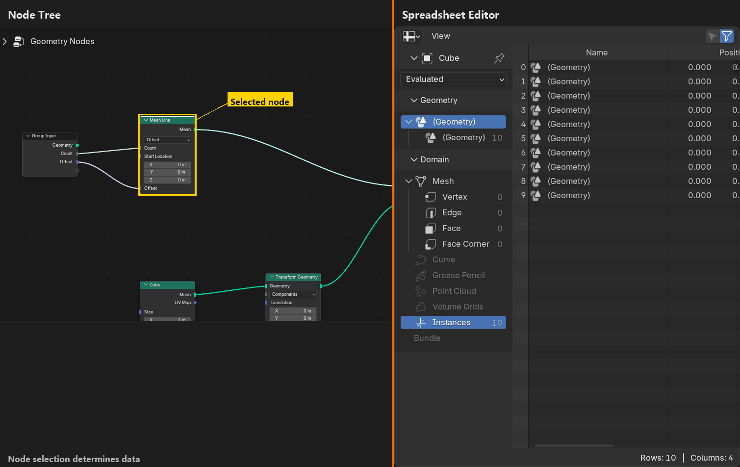
💡 Systematic Debugging Process
Step-by-Step Problem Solving:
Step 1: Define Expected vs Actual
- What should happen? (Be specific)
- What actually happens? (Describe precisely)
- Write it down if complex
Step 2: Isolate the Problem
- Trace data flow from Input to Output
- Use Viewer node to check each stage
- Find FIRST point where output differs from expectation
- Problem is in that node or just before
Step 3: Check Node Configuration
- Verify all inputs connected correctly
- Check parameter values (not zero, not extreme)
- Review dropdowns (mode, type, domain)
- Look for red error indicators
Step 4: Verify Data Types
- Check socket colors match (green to green, etc.)
- Use Spreadsheet to verify data exists and is correct type
- Add conversions if types mismatched
Step 5: Simplify and Test
- Mute complex parts
- Test with simple values first
- Add complexity back gradually
- Document what works, what doesn't
Step 6: Consult Resources
- Hover tooltips (describe node purpose)
- Blender documentation
- Community forums (Blender Artists, Stack Exchange)
- Search for specific error messages
Common Misconceptions
🤔 Myths and Misunderstandings
Misconception 1: "More nodes = better result"
- Reality: Simpler is often better (faster, easier to debug)
- Use minimum nodes needed to achieve goal
- Complex ≠ professional
Misconception 2: "Instances are the same as duplicates"
- Reality: Instances reference source, duplicates copy geometry
- Instances: Memory efficient, can't edit individually
- Realized: Memory heavy, can edit individually
- Choose based on needs, not habit
Misconception 3: "Node order in editor matters"
- Reality: Only connections matter, not visual layout
- Blender evaluates based on dependencies, not left-to-right position
- Organize for YOUR readability, doesn't affect execution
Misconception 4: "I need to learn all nodes"
- Reality: Know categories, look up specifics as needed
- Even experts don't memorize every node
- Focus on understanding principles, not memorizing nodes
Misconception 5: "Geometry Nodes is programming"
- Reality: It's visual logic, not code
- No syntax to memorize
- More like building with LEGO than writing text
- Programming experience helps but not required
When to Ask for Help
✅ Getting Unstuck
Before Asking:
- Spend 15-30 minutes debugging yourself (builds skills)
- Check this troubleshooting section
- Search error message online
- Try simplifying problem
When to Ask:
- Stuck after genuine effort (not immediately)
- Found potential bug (unusual behavior)
- Need advice on approach (multiple valid methods)
How to Ask (Effective Help Requests):
- Describe goal: "I'm trying to create [X]"
- Explain problem: "I expect [Y], but seeing [Z]"
- Show what you tried: "I attempted [steps], result was [outcome]"
- Provide screenshots: Node tree + viewport
- Share file if possible: (via Blend-Exchange or Pasteall)
- Include Blender version: Nodes change between versions
Where to Ask:
- Blender Artists Forum: Great community, detailed responses
- Blender Stack Exchange: Q&A format, searchable
- Reddit r/blender: Active, visual-friendly
- Blender Discord: Real-time chat, quick help
💭 Debugging is Learning: Every problem you solve makes you stronger. That frustrating hour spent tracking down a connection issue? You just learned data flow deeply. That performance problem you optimized? You now understand efficiency. Errors aren't failures—they're learning opportunities disguised as obstacles. The best Geometry Nodes users aren't those who never encounter problems; they're those who've learned to solve them systematically. Welcome every challenge as a chance to level up!
🎯 Troubleshooting Summary
Key Debugging Skills:
- Visual issues: Check connections, verify output path, watch for generators replacing input
- Connection issues: Match socket types, use conversion nodes
- Performance issues: Reduce counts, avoid realizing instances unnecessarily
- Logic issues: Verify IDs for randomness, check attribute domains
- Debug tools: Viewer node, Spreadsheet, mute nodes, simplify
- Process: Define expected vs actual, isolate problem, check config, verify types
Remember: Every expert was once confused. Debugging is the path to mastery!
🚀 Next Steps and Learning Path
Congratulations! You've completed your introduction to Geometry Nodes. You understand the interface, know the essential nodes, built real projects, and learned to troubleshoot issues. But this is just the beginning—Geometry Nodes is vast, and you've only scratched the surface. The good news? You now have the foundation to explore confidently. In this final section, we'll map out your learning journey: what to learn next, in what order, and how to practice effectively. Think of this as your roadmap from competent beginner to confident creator. Let's chart your path forward!
🎯 Where You Are Now
Skills Acquired:
- Interface navigation and workspace setup
- Node anatomy and connection mechanics
- Data flow and type systems understanding
- Essential node toolkit (primitives, instances, math, utilities)
- Real project completion (cube stack, procedural fence)
- Troubleshooting and debugging strategies
What This Enables:
- Create simple procedural systems independently
- Understand and modify existing node setups
- Follow tutorials with comprehension
- Solve basic problems systematically
You're ready for intermediate concepts!
Immediate Next Topics
✅ Skill Level 2: Intermediate Concepts
Study These Next (In Order):
1. Field-Based Operations
- What it is: Understanding attributes as fields (data that varies across geometry)
- Why important: Core to advanced Geometry Nodes techniques
- Key concepts:
- Fields vs single values
- Per-element variation
- Selection fields (masks)
- Combining fields with math
- Practice project: Gradient-based selection (delete faces by position, color by height)
2. Noise and Randomness
- What it is: Adding natural variation and organic patterns
- Why important: Makes procedural content look natural, not computer-generated
- Key nodes:
- Random Value (you've used this!)
- White Noise Texture
- Wave Texture
- Voronoi Texture
- Practice project: Scattered rocks with size/rotation variation, procedural terrain with noise displacement
3. Proximity and Raycasting
- What it is: Detecting distances and intersections
- Why important: Enables context-aware placement and reactions
- Key nodes:
- Geometry Proximity
- Raycast
- Sample Nearest (Surface, Index)
- Practice project: Ivy growing on wall (instances only appear near surface), snow accumulation on top surfaces
4. Advanced Curve Operations
- What it is: Manipulating and analyzing curves
- Why important: Curves power many procedural systems (paths, profiles, distributions)
- Key concepts:
- Curve parameter vs length
- Trimming curves
- Sample Curve node
- Curve tangents and normals
- Practice project: Chain/rope that follows curve with realistic links, procedural road with lane markings
5. Mesh Boolean Operations
- What it is: Combining meshes with union, difference, intersection
- Why important: Create complex forms from simple shapes
- Key node: Mesh Boolean
- Practice project: Procedural building with door/window cutouts, Swiss cheese effect
Advanced Topics (Level 3)
💡 Master-Level Concepts
Tackle After Mastering Intermediates:
1. Simulation Nodes (Blender 3.4+)
- Time-based animations
- Particle systems
- Physics-based motion
- Example: Swarming behavior, growing plants
2. Volume Operations
- Mesh to Volume conversion
- Volume manipulation
- Volume to Mesh
- Example: Smooth boolean operations, volumetric effects
3. Custom Node Groups
- Creating reusable node groups
- Building personal library
- Group input/output design
- Example: Custom scatter system, architectural element generators
4. Repeat Zones (Loops)
- Iterative operations
- Accumulation over iterations
- Complex recursive patterns
- Example: Fractal generation, L-systems for plants
5. Attribute Math and Complex Fields
- Vector field manipulation
- Gradient operations
- Multi-attribute combinations
- Example: Flow fields, force-based deformations
Learning Resources
📚 Where to Learn More
Official Resources:
- Blender Manual: docs.blender.org/manual/en/latest/modeling/geometry_nodes/
- Comprehensive node reference
- Updated with each Blender version
- Technical but accurate
- Blender Studio: studio.blender.org
- Professional production files
- Shows real-world usage
- Some content requires Cloud subscription
Video Tutorials (YouTube):
- Blender Guru: Beginner-friendly, clear explanations
- Default Cube: Focused Geometry Nodes tutorials
- Bradley Animation: Practical, project-based
- Erindale: Advanced techniques, deep dives
- CGMatter: Creative projects, quick tips
- Blender Daily: News and feature showcases
Community Resources:
- Blender Artists Forum: blenderartists.org
- Geometry Nodes subforum
- Work-in-progress threads
- Helpful community
- Blender Stack Exchange: blender.stackexchange.com
- Q&A format
- Searchable archive
- Specific problem solving
- Reddit r/blender:
- Active community
- Daily inspiration
- Quick questions thread
Paid Courses (Optional but Structured):
- Udemy: Various instructors, wait for sales
- CG Cookie: Structured learning paths
- Blender Cloud: Official training content
- Note: Free resources are often sufficient—pay for structure/support if desired
Practice Projects (Skill Builders)
✅ Projects to Build Your Skills
Beginner Projects (Start Here):
- Procedural City Grid
- Grid of points → Building instances
- Random heights, sizes
- Simple but impressive result
- Skills: Instancing, randomness, transforms
- Stone Wall/Brick Pattern
- Grid → Offset alternate rows → Instance bricks
- Variation in mortar gaps
- Skills: Grid manipulation, modulo operations, instancing
- Forest/Tree Distribution
- Mesh surface → Distribute Points → Tree instances
- Random scale/rotation
- Density control
- Skills: Surface distribution, randomness, instance variation
Intermediate Projects:
- Procedural Staircase
- Mesh Line → Instance steps → Railing on sides
- Parameters: Step count, height, width
- Spiral variation (advanced)
- Skills: Precise positioning, transforms, curve operations
- Cable/Pipe Along Curve
- Curve → Curve to Mesh → Add connectors at ends
- Automatic sagging (noise displacement)
- Skills: Curve operations, mesh generation, deformation
- Terrain with Features
- Grid → Noise displacement → Roads carved out
- Trees on slopes only
- Water at low elevations
- Skills: Noise, selection masks, proximity
Advanced Projects:
- Parametric Building Generator
- Floor count, window spacing, style controls
- Automatic window/door placement
- Roof variations
- Skills: Complex parameter systems, boolean operations, conditional logic
- Animated Growth System
- Mesh grows over time
- Branches split and extend
- Requires simulation nodes
- Skills: Simulation, time-based animation, accumulation
Effective Practice Strategies
💡 How to Learn Efficiently
Strategy 1: Deliberate Practice
- Don't just follow tutorials: Pause and recreate without looking
- Add variations: "What if I changed this parameter?" "Can I make it work differently?"
- Break and fix: Intentionally break setup, then repair it (teaches debugging)
- Explain aloud: Describe what each node does (solidifies understanding)
Strategy 2: Project-Based Learning
- Choose projects slightly above skill level (challenging but achievable)
- Complete full projects: Start to finish, not just "good enough"
- Document your work: Save files with notes, create personal wiki
- Share for feedback: Post on forums, learn from critiques
Strategy 3: Concept Mastery
- Focus on one concept at a time: This week: fields. Next week: proximity.
- Build multiple projects using same concept: Repetition with variation = mastery
- Teach others: Explain concepts to friends/community (teaching = deepest learning)
Strategy 4: Reverse Engineering
- Download example files: Blend-Exchange, Gumroad freebies
- Dissect node trees: Why is this node here? What if I remove it?
- Recreate from memory: Study setup, close file, rebuild it yourself
- Improve existing setups: Add features, optimize, fix limitations
Strategy 5: Build a Personal Library
- Save reusable setups: Node groups for common tasks
- Document parameters: What does each input control?
- Organize by category: Scattering, architecture, natural, utilities
- Iterate and improve: Update library as you learn better methods
Common Learning Pitfalls to Avoid
⚠️ Don't Fall Into These Traps
Pitfall 1: Tutorial Hell
- Problem: Following tutorials endlessly without creating original work
- Why it's bad: You can follow but can't create independently
- Solution: After every tutorial, create something similar but different (apply concept, don't copy)
Pitfall 2: Complexity Obsession
- Problem: Believing complex trees are better/more professional
- Why it's bad: Complexity ≠ quality. Simple often better.
- Solution: Always ask "Can I simplify this?" Professional = elegant, not convoluted
Pitfall 3: Skipping Fundamentals
- Problem: Jumping to advanced features without mastering basics
- Why it's bad: Weak foundation = confusion in advanced topics
- Solution: Master this lesson's content before moving to simulation/volumes
Pitfall 4: No Documentation
- Problem: Not saving useful setups or taking notes
- Why it's bad: Relearning same concepts repeatedly
- Solution: Build personal reference library, document discoveries
Pitfall 5: Isolation
- Problem: Learning alone without community engagement
- Why it's bad: Miss tips, stay stuck longer, lack motivation
- Solution: Join forums, share work, ask questions, help others
Setting Learning Goals
✅ Create Your Learning Plan
30-Day Plan (Post-Course):
Week 1: Solidify Fundamentals
- Recreate both course projects from memory
- Experiment with 5 variations of each
- Build simple city grid project
- Goal: Confidence with basics, no reference needed
Week 2: Fields and Selection
- Study field-based operations tutorial
- Create gradient selection project
- Build position-based color system
- Goal: Understand fields vs values
Week 3: Noise and Natural Variation
- Learn noise texture nodes
- Create scattered forest with variation
- Build simple terrain with displacement
- Goal: Make procedural content look organic
Week 4: Curves and Complex Systems
- Advanced curve operations tutorial
- Build cable/rope system
- Create custom architectural element
- Goal: Combine multiple concepts into complex system
After 30 Days:
- Choose specialization (architecture, nature, abstract, animation)
- Build portfolio piece in that area
- Share with community for feedback
- Iterate based on critiques
Staying Current
📰 Keeping Up with Geometry Nodes
Geometry Nodes Evolves Rapidly:
- New nodes added in each Blender version
- Performance improvements
- New features (simulation zones, repeat zones, etc.)
- Best practices change as system matures
How to Stay Updated:
- Blender Development Blog: code.blender.org/category/geometry-nodes/
- Release Notes: Read "What's New" when updating Blender
- Follow Key Developers: Twitter/Mastodon (Jacques Lucke, Hans Goudey)
- YouTube Channels: Subscribe to Geometry Nodes-focused creators
- Community Pulse: Check Blender Artists weekly
Version Migration:
- Save files with Blender version in filename (project_4_0.blend)
- Test old setups in new versions (usually work, sometimes need updates)
- Learn new features incrementally (don't feel pressure to use everything)
- Stable = good. Cutting edge = exciting but risky for production
Final Encouragement
💪 You've Got This!
Remember:
- Every expert was once a beginner: That intimidating node tree on ArtStation? Built one node at a time, just like you're learning.
- Confusion is part of learning: If you're not confused sometimes, you're not pushing yourself. Embrace the challenge!
- Community is powerful: Thousands of people learning alongside you. Ask questions, share discoveries, help others.
- Procedural thinking is valuable: Skills transfer beyond Blender—Houdini, Unreal, Unity all use similar concepts.
- Have fun: Geometry Nodes is playground, not classroom. Experiment, break things, discover happy accidents!
Your Journey Starts Now:
- You have the foundation
- You know where to go next
- You can learn anything with practice
- The only limit is your creativity
Go build something amazing. We can't wait to see what you create!
💭 Final Wisdom: Geometry Nodes isn't just a tool—it's a new way of thinking about 3D content creation. Instead of "How do I model this?", you start asking "What system could generate this?" That shift in mindset is powerful. You're not just learning buttons and menus; you're learning to think procedurally, to design systems, to solve problems with logic and creativity. This skill compounds over time. Every project makes you stronger. Every problem solved builds your intuition. A year from now, you'll look back at today's confusion with a smile, amazed at how far you've come. Trust the process. Stay curious. Keep building. Welcome to the world of procedural content creation—your creative toolkit just expanded infinitely!
🎓 Lesson Summary
✅ What You Learned
Core Understanding:
- Geometry Nodes fundamentals: What they are, why they matter, how they revolutionize 3D workflow
- Interface mastery: Workspaces, editors, navigation, node tree management
- Node mechanics: Anatomy, sockets, connections, data types, execution flow
- Data flow principles: How geometry travels through nodes, pass-through vs replacement, joining streams
Essential Skills:
- Node toolkit: Primitives, instances, transforms, attributes, math, utilities, curves
- Project completion: Built cube stack and procedural fence from scratch
- Parameter exposure: Made systems user-friendly with controllable inputs
- Troubleshooting: Systematic debugging, common issues, problem-solving strategies
Practical Applications:
- Instance-based distribution systems
- Curve-following geometry generation
- Multi-component procedural assets
- Parametric design workflows
🔑 Key Takeaways
- Procedural = Flexible: Change parameters anytime, adapt to any situation, infinite variations from one setup
- Nodes are logic: Each node performs single task, complex systems built from simple parts
- Data flow matters: Trace connections from input to output, understand what data exists where
- Instance efficiently: Copy smartly, not wastefully—instances over realized geometry when possible
- Think systemically: Don't model individual results, design systems that generate results
- Practice deliberately: Following tutorials < applying concepts independently
- Debug systematically: Define expected vs actual, isolate problem, verify configuration, test solutions
- Community accelerates learning: Share, ask, help others, learn from masters
📋 Recommended Next Actions
- Immediate: Recreate both projects from memory (no tutorial reference)
- This Week: Build the city grid beginner project
- This Month: Complete 30-day learning plan
- This Quarter: Build portfolio piece, share with community
- Ongoing: Practice regularly, stay current, help others
🎉 Congratulations!
You've Completed Geometry Nodes Introduction
You now possess the foundation to create procedural magic in Blender. Every complex node tree you see online started exactly where you are now. The difference between "impossible" and "done" is simply practice and persistence.
Your creative superpowers have been unlocked.
Now go forth and build procedural wonders! 🚀✨